DESCRIPTION
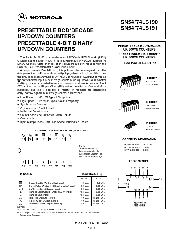
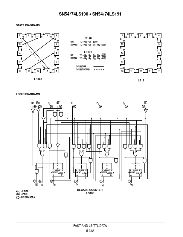
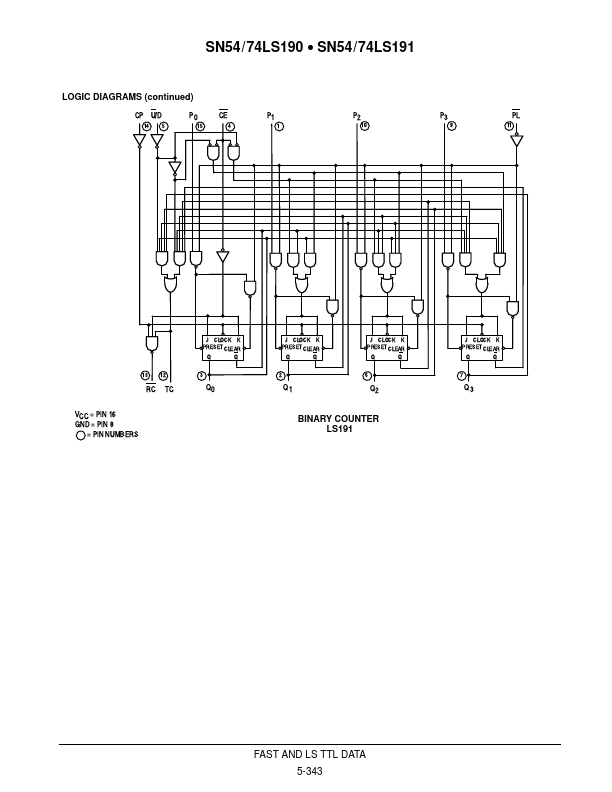
Each circuit contains four master / slave flip-flops, with internal gating and steering logic to provide individual preset, count-up and count-down operations. Each circuit has an asynchronous parallel load capability permitting the counter to be preset to any desired number. When the Parallel Load (PL) input is LOW, information present on the Parallel Data inputs (P0 – P3) is loaded into the counter and appears on the Q outputs. This operation overrides the counting functions, as indicated in the Mode Select Table. A HIGH signal on the CE input inhibits counting. When CE is LOW, internal state change are initiated synchronously by the LOW-to-HIGH transition of the clock input. The direction of counting is determined by the U/D input signal, as indicated in the Mode Select Table. When counting is to be enabled, the CE signal can be made LOW when the clock is in either state. However, when counting is to be inhib Motorola