DESCRIPTION
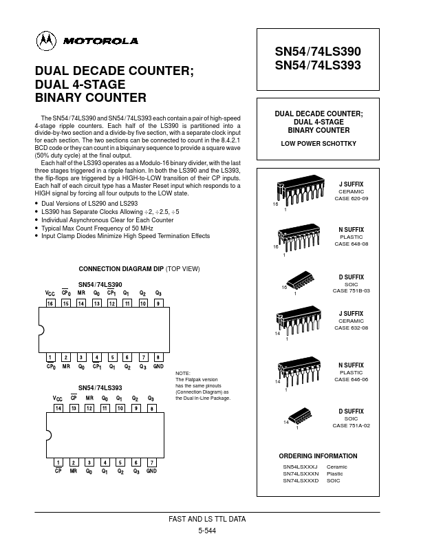
Each half of the SN54 / 74LS393 operates in the Modulo 16 binary sequence, as indicated in the ÷ 16 Truth Table. Thus state changes of the Q outputs do not occur simultaneously. This means that logic signals derived from combinations of these outputs will be subject to decoding spikes and, therefore, should not be used as clocks for other counters, registers or flip-flops. A HIGH signal on MR forces all outputs to the LOW state and prevents counting. Each half of the LS390 contains a ÷ 5 section that is independent except for the common MR function. The ÷ 5 section operates in 4.2.1 binary sequence, as shown in the ÷ 5 Truth Table, with the third stage output exhibiting a 20% duty cycle when the input frequency is constant. To obtain a ÷10 function having a 50% duty cycle output, connect the input signal to CP1 and connect the Q3 output to the CP0 input; the Q0 output provides the desired 50% duty cycle output. If the input frequency is connected to CP0 and the Q0 output is connected to CP1, a decade divider operating in the 8.4.2.1 BCD code is obtained, as shown in the BCD Truth Table. Motorola