Motorola 74LS670
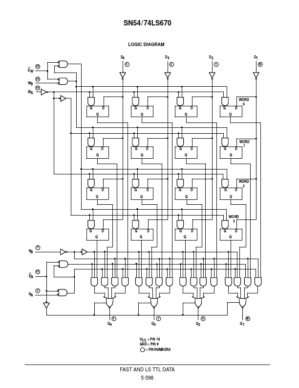
74LS670 is a high-speed, low-power 4 x 4 Register File organized as four words by four bits. The 3-state outputs make it possible to connect up to 128 outputs to increase the word capacity up to 512 words. The SN54 / 74LS170 provides a similar function to this device but it features open-collector outputs.| Part No. | 74LS670 |
|---|---|
| Datasheet | 74LS670 Download |
| Manufacturer |  Motorola |
| Description | 4x4 REGISTER |
| Buy | Stock & Price |
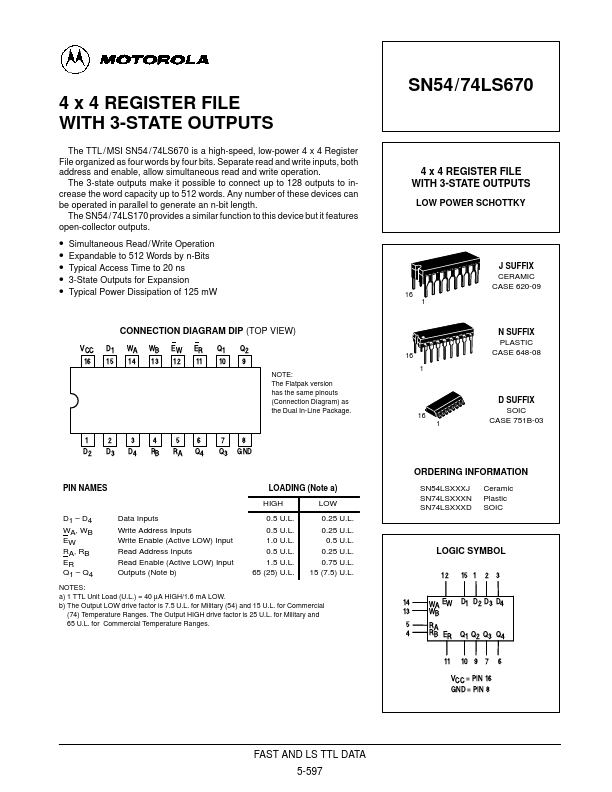
SN54/74LS670 4 x 4 REGISTER FILE WITH 3-STATE OUTPUTS The TTL / MSI SN54 / Separate read and write inputs, both address and enable, allow simultaneous read and write operation. Any number of these devices can be operated in parallel to generate an n-bit length. 4 x 4 REGISTER FILE WITH 3-STATE OUTPUTS LOW POWER SCHOTTKY
●
●
●
●
● Simultaneous Read/ Write Operation Expandable to 512 Words by n-Bits Typical Access Time to 20 ns 3-State Outputs for Expansion Typical Power Dissipation of 125 mW J SUFFIX CERAMIC CASE 620-09 16 1 CONNECTION DIAGRAM DIP (TOP VIEW) VCC 16 D1 15 WA 14 WB 13 EW 12 ER 11 Q1 10 Q2 9 NOTE: The Flatpak version has the same pinouts (Connection Diagram) as the Dual In-Line Package. 16 1 N SUFFIX PLASTIC CASE 648-08 16 1 D SUFFIX SOIC CASE 751B-03 1 D2 2 D3 3 D4 4 RB 5 RA 6 Q4 7 Q3 8 GND ORDERING INFORMATION PIN NAMES LOADING (Note a) HIGH D1 – D4 WA, WB EW RA, RB ER Q1 – Q4 Data Inputs Write Address Inputs Write Enable (Active LOW) Input Read Address Inputs Read Enable (Active LOW) Input Outputs (Note b) 0.5 U.L.
●
●
●
●
● Simultaneous Read/ Write Operation Expandable to 512 Words by n-Bits Typical Access Time to 20 ns 3-State Outputs for Expansion Typical Power Dissipation of 125 mW J SUFFIX CERAMIC CASE 620-09 16 1 CONNECTION DIAGRAM DIP (TOP VIEW) VCC 16 D1 15 WA 14 WB 13 EW 12 ER 11 Q1 10 Q2 9 NOTE: The Flatpak version has the same pinouts (Connection Diagram) as the Dual In-Line Package. 16 1 N SUFFIX PLASTIC CASE 648-08 16 1 D SUFFIX SOIC CASE 751B-03 1 D2 2 D3 3 D4 4 RB 5 RA 6 Q4 7 Q3 8 GND ORDERING INFORMATION PIN NAMES LOADING (Note a) HIGH D1 – D4 WA, WB EW RA, RB ER Q1 – Q4 Data Inputs Write Address Inputs Write Enable (Active LOW) Input Read Address Inputs Read Enable (Active LOW) Input Outputs (Note b) 0.5 U.L.