DESCRIPTION
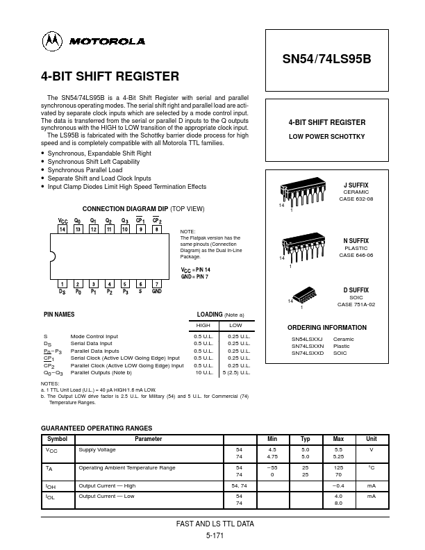
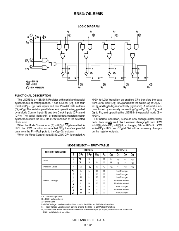
The serial or parallel mode of operation is controlled by a Mode Control input (S) and two Clock Inputs (CP1) and (CP2). The serial (right-shift) or parallel data transfers occur synchronous with the HIGH to LOW transition of the selected clock input. When the Mode Control input (S) is HIGH, CP2 is enabled. A HIGH to LOW transition on enabled CP2 transfers parallel data from the P0 – P3 inputs to the Q0 – Q3 outputs. When the Mode Control input (S) is LOW, CP1 is enabled. A HIGH to LOW transition on enabled CP1 transfers the data from Serial input (DS) to Q0 and shifts the data in Q0 to Q1, Q1 to Q2, and Q2 to Q3 respectively (right-shift). A left-shift is accomplished by externally connecting Q3 to P2, Q2 to P1, and Q1 to P0, and operating the LS95B in the parallel mode (S = HIGH). For normal operation, S should only change states when both Clock inputs are LOW. However, changing S from LOW to HIGH while CP2 is HIGH, or changing S from HIGH to LOW while CP1 is HIGH and CP2 is LOW will not cause any changes on the register outputs. Motorola