MC14516B
Overview
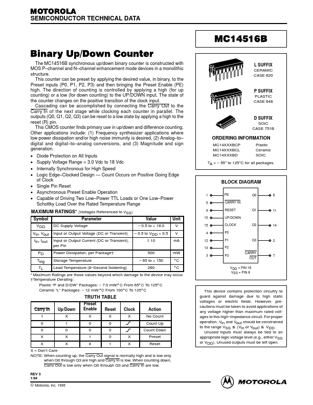
MOTOROLA SEMICONDUCTOR TECHNICAL DATA MC14516B Binary Up/Down Counter The MC14516B synchronous up/down binary counter is constructed with MOS P–channel and N–channel enhancement mode devices in a mon...
| Part | MC14516B |
|---|---|
| Description | Binary Up/Down Counter |
| Manufacturer | Motorola Semiconductor |
| Size | 258.18 KB |
MOTOROLA SEMICONDUCTOR TECHNICAL DATA MC14516B Binary Up/Down Counter The MC14516B synchronous up/down binary counter is constructed with MOS P–channel and N–channel enhancement mode devices in a mon...
| Part Number | Manufacturer | Description |
|---|---|---|
| MC145163 | Unknown Manufacturer | MC145163 PLL Integrated Circuits |
| MC1451A | PMD | Advanced Step Motor Control Chipset |