MC14569B
MC14569B is Programmable Divide-By-N Dual 4-Bit Binary/BCD Down Counter manufactured by Motorola Semiconductor.
MOTOROLA
SEMICONDUCTOR TECHNICAL DATA
MC14569B Programmable Divide-By-N Dual 4-Bit Binary/BCD Down Counter
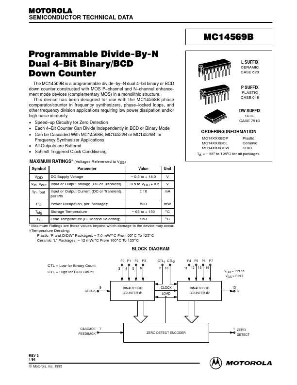
The MC14569B is a programmable divide- by- N dual 4- bit binary or BCD down counter constructed with MOS P- channel and N- channel enhancement mode devices (plementary MOS) in a monolithic structure. This device has been designed for use with the MC14568B phase parator/counter in frequency synthesizers, phase- locked loops, and other frequency division applications requiring low power dissipation and/or high noise immunity.
- Speed- up Circuitry for Zero Detection
- Each 4- Bit Counter Can Divide Independently in BCD or Binary Mode
- Can be Cascaded With MC14568B, MC14522B or MC14526B for Frequency Synthesizer Applications
- All Outputs are Buffered
- Schmitt Triggered Clock Conditioning MAXIMUM RATINGS- (Voltages Referenced to VSS)
Symbol VDD Parameter DC Supply Voltage L SUFFIX CERAMIC CASE 620
P SUFFIX PLASTIC CASE 648
DW SUFFIX SOIC CASE 751G
ORDERING INFORMATION
MC14XXXBCP MC14XXXBCL MC14XXXBDW Plastic Ceramic SOIC
ÎÎÎÎÎÎÎÎÎÎÎÎÎÎÎÎÎÎÎÎÎ ÎÎÎÎÎÎÎÎÎÎÎÎÎÎÎÎÎÎÎÎÎ ÎÎÎÎÎÎÎÎÎÎÎÎÎÎÎÎÎÎÎÎÎ ÎÎÎÎÎÎÎÎÎÎÎÎÎÎÎÎÎÎÎÎÎ
Value Unit V V m A m W
- 0.5 to + 18.0 Vin, Vout Iin, Iout PD Tstg TL Input or Output Voltage (DC or Transient) Input or Output Current (DC or Transient), per Pin Power Dissipation, per Package† Storage Temperature Lead Temperature (8- Second Soldering)
- 0.5 to VDD + 0.5 ± 10 500
- 65 to + 150 260
TA =
- 55° to 125°C for all packages.
_C _C
- Maximum Ratings are those values beyond which damage to the device may occur. †Temperature Derating: Plastic “P and D/DW” Packages:
- 7.0 m W/_C From 65_C To 125_C Ceramic “L” Packages:
- 12 m W/_C From 100_C To 125_C
BLOCK DIAGRAM
P0 P1 P2 P3 CTL = Low for Binary Count CTL = High for BCD Count 3 4 5 6 CTL1 CTL2 2 10 P4 P5 P6 P7 11 12 13 14 VDD = PIN 16 VSS = PIN 8 15
CLOCK
BINARY/BCD COUNTER #1
CLOCK LOAD
BINARY/BCD COUNTER #2
CASCADE 7 FEEDBACK
ZERO DETECT ENCODER
1 ZERO DETECT
REV 3 1/94
©MOTOROLA...