MC33219A
Overview
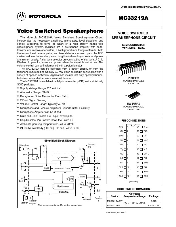
Order this document by MC33219A/D MC33219A Voice Switched Speakerphone The Motorola MC33219A Voice Switched Speakerphone Circuit incorporates the necessary amplifiers, attenuators, level detectors, a...
Order this document by MC33219A/D MC33219A Voice Switched Speakerphone The Motorola MC33219A Voice Switched Speakerphone Circuit incorporates the necessary amplifiers, attenuators, level detectors, a...