Datasheet4U Logo Datasheet4U.com

MC44864 - PLL TUNING CIRCUIT

Description

Pin 6, 7, 8 9 10, 11 12, 20 13 14, 15, 16, 17 18 19 1 2 3 4 5 Symbol DA1, DA2, DA3 VCC1 HF1, HF2 Gnd CA B1, B3, B5, B7 SCL SDA XTAL PHO Amp In VCC2 VTUN D/A output control voltages Positive supply of the circuit (except DACs) HF input from local oscillator Ground Chip Address Band buffer output can

Features

  • and function of the internal blocks is given below. Automatic Tuner Alignment The circuit generates the tuning voltage through the PLL. The output voltages of the D/A converters are equal to the tuning voltage plus a positive or negative offset of up to 31 steps. During the automatic alignment one first lets the PLL lock to the appropriate frequency and then searches for the optimum value of the other varactor voltages. The digital word for each voltage value is stored in a nonvolatile memory (N.

📥 Download Datasheet

Full PDF Text Transcription

Click to expand full text
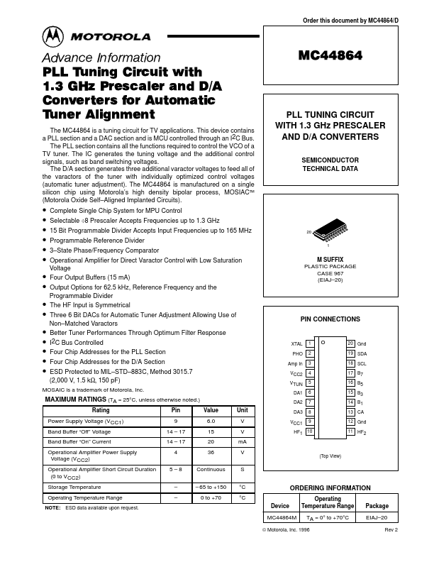
Order this document by MC44864/D Advance Information PLL Tuning Circuit with 1.3 GHz Prescaler and D/A Converters for Automatic Tuner Alignment The MC44864 is a tuning circuit for TV applications. This device contains a PLL section and a DAC section and is MCU controlled through an I2C Bus. The PLL section contains all the functions required to control the VCO of a TV tuner. The IC generates the tuning voltage and the additional control signals, such as band switching voltages. The D/A section generates three additional varactor voltages to feed all of the varactors of the tuner with individually optimized control voltages (automatic tuner adjustment).
Published: |