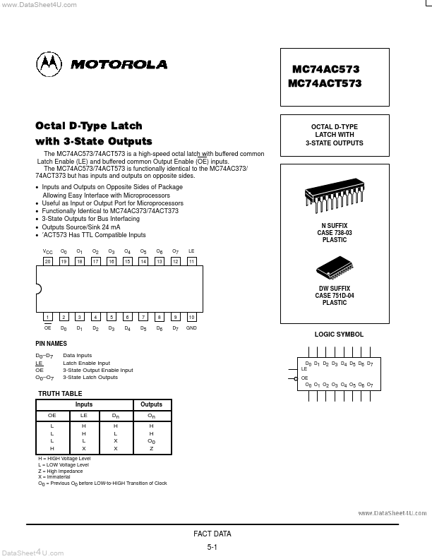
DESCRIPTION
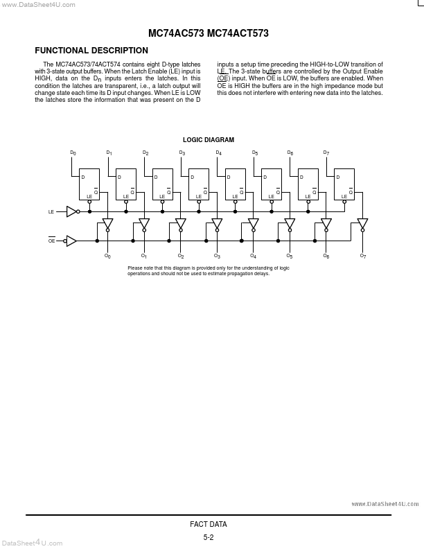
The MC74AC573/74ACT574 contains eight D-type latches with 3-state output buffers. In this condition the latches are transparent, i.e., a latch output will change state each time its D input changes. When LE is LOW the latches store the information that was present on the D inputs a setup time preceding the HIGH-to-LOW transition of LE. The 3-state buffers are controlled by the Output Enable (OE) input. When OE is LOW, the buffers are enabled. When OE is HIGH the buffers are in the high impedance mode but this does not interfere with entering new data into the latches. LOGIC DIAGRAM D0 D1 D2 D3 D4 D5 D6 D7 D Q D Q D Q D Q D Q D Q D Q D Q LE LE LE LE LE LE LE LE LE OE O0 O1 O2 O3 O4 O5 O6 O7 Please note that this diagram is provided only for the understanding of logic operations and should not be used to estimate propagation delays. FACT DATA DataSheet 4 U .com 5-2 MC74AC573 MC74ACT573 MAXIMUM RATINGS
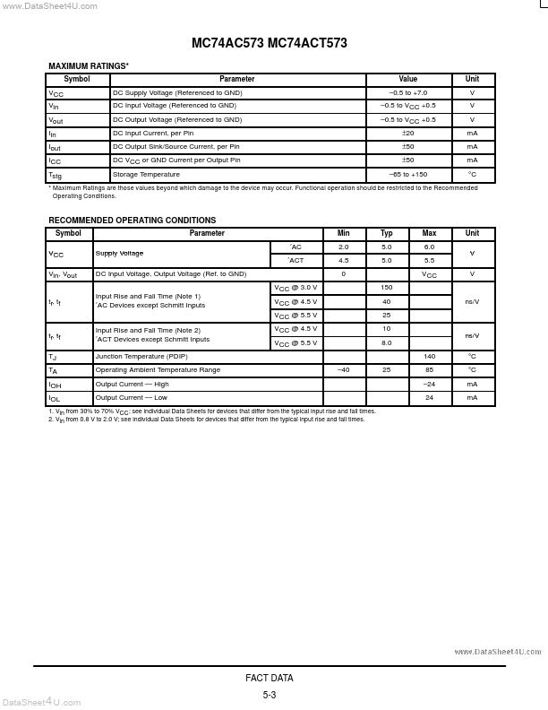
* Symbol VCC Vin Vout Iin Iout ICC Tstg Parameter DC Supply Voltage (Referen... Motorola