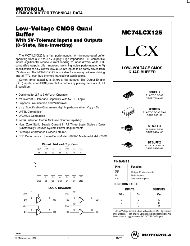
MC74LCX125
MC74LCX125 is LOW-VOLTAGE CMOS QUAD BUFFER manufactured by Motorola Semiconductor.
MOTOROLA
SEMICONDUCTOR TECHNICAL DATA
Low-Voltage CMOS Quad Buffer
With 5V-Tolerant Inputs and Outputs (3-State, Non-Inverting)
The MC74LCX125 is a high performance, non- inverting quad buffer operating from a 2.7 to 3.6V supply. High impedance TTL patible inputs significantly reduce current loading to input drivers while TTL patible outputs offer improved switching noise performance. A VI specification of 5.5V allows MC74LCX125 inputs to be safely driven from 5V devices. The MC74LCX125 is suitable for memory address driving and all TTL level bus oriented transceiver applications. Current drive capability is 24m A at the outputs. The Output Enable (OEn) inputs, when HIGH, disable the outputs by placing them in a HIGH Z condition.
LOW- VOLTAGE CMOS QUAD BUFFER
- -
- -
- -
- -
Designed for 2.7 to 3.6V VCC Operation 5V Tolerant
- Interface Capability With 5V TTL Logic Supports Live Insertion and Withdrawal IOFF Specification Guarantees High Impedance When VCC = 0V LVTTL patible LVCMOS patible 24m A Balanced Output Sink and Source Capability
14 1
D SUFFIX PLASTIC SOIC CASE 751A- 03
14 1
M SUFFIX PLASTIC SOIC EIAJ CASE 965- 01
Near Zero Static Supply Current in All Three Logic States (10µA) Substantially Reduces System Power Requirements
- Latchup Performance Exceeds 500m A
14 1
SD SUFFIX PLASTIC SSOP CASE 940A- 03
- ESD Performance: Human Body Model >2000V; Machine Model >200V
Pinout: 14- Lead (Top View)
VCC 14 OE3 13 D3 12 O3 11 OE2 10 D2 9 O2 8
14 1
DT SUFFIX PLASTIC TSSOP CASE 948G- 01
PIN NAMES
Pins OEn Dn On Function Output Enable Inputs Data Inputs 3- State Outputs
1 OE0
2 D0
3 O0
4 OE1
5 D1
6 O1
7 GND
FUNCTION TABLE LOGIC DIAGRAM
OE0 D0 OE1 D1 1 2 4 5 6 O1 3 O0 OE2 D2 OE3 D3 10 OEn 9 13 12 11 O3 8 O2 L L H INPUTS Dn L H X OUTPUTS On L H Z
H = High Voltage Level; L = Low Voltage Level; Z = High Impedance State; X = High or Low Voltage Level and Transitions Are Acceptable, for ICC reasons, DO NOT FLOAT Inputs
11/96
© Motorola, Inc....