Motorola MCR100-4
Silicon Controlled Rectifiers
| Part No. | MCR100-4 |
|---|---|
| Datasheet | MCR100-4 Download |
| Manufacturer |  Motorola |
| Description | Silicon Controlled Rectifiers |
| Buy | Stock & Price |
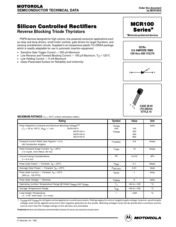
MAXIMUM RATINGS
(TJ = 25°C unless otherwise noted.) Rating Peak Repetitive Forward and Reverse Blocking Voltage(1) (TJ = 25 to 125°C, RGK = 1 kΩ MCR100-3 MCR100-4 MCR100-6 MCR100-8 Forward Current RMS (See Figures 1 & 2) (All Conduction Angles) Peak Forward Surge Current, TA = 25°C (1/2 Cycle, Sine Wave, 60 Hz) Circuit Fusing Considerations (t = 8.3 ms) Peak Gate Power — Forward, TA = 25°C Average Gate Power — Forward, TA = 25°C Peak Gate Current — Forward, TA = 25°C (300 µs, 120 PPS) Peak Gate Voltage — Reverse Operating Junction Temperature Range @ Rated VRRM and VDRM Storage Temperature Range Lead Solder Temperature ( 1/16I from case, 10 s max) Symbol VDRM and VRRM Value 100 200 400 600 0.8 10 0.415 0.1 0.01 1 5 –40 to +125 –40 to +150 +230 Amps Amps A2s Watts Watt Amp Volts °C °C °C Unit Volts IT(RMS) ITSM I2t PGM PGF(AV) IGFM VGRM TJ Tstg — t 1. VDRM and VRRM for all types can be applied on a continuous basis. Ratings apply for zero or negative gate voltage; however, positive gate voltage shall not be applied concurrent with negative potential on the anode.