Motorola MCR16
Silicon Controlled Rectifiers
| Part No. | MCR16 |
|---|---|
| Datasheet | MCR16 Download |
| Manufacturer |  Motorola |
| Description | Silicon Controlled Rectifiers |
| Buy | Stock & Price |
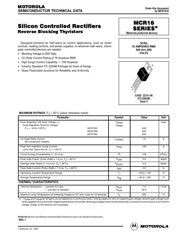
MAXIMUM RATINGS
(TJ = 25°C unless otherwise noted) Parameter Peak Repetitive Off-State Voltage (1) Peak Repetitive Reverse Voltage (TJ = –40 to 125°C) Symbol VDRM VRRM MCR16D MCR16M MCR16N IT(RMS) ITSM I2t PGM PG(AV) IGM TJ Tstg 400 600 800 16 160 106 5.0 0.5 2.0 – 40 to +125 – 40 to +150 A A A2sec Watts Watts A °C °C Value Unit Volts On-State RMS Current (All Conduction Angles) Peak Non-repetitive Surge Current (One Half Cycle, 60 Hz, TJ = 125°C) Circuit Fusing Consideration (t = 8.3 ms) Peak Gate Power (Pulse Width ≤ 1.0 µs, TC = 80°C) Average Gate Power (t = 8.3 ms, TC = 80°C) Peak Gate Current (Pulse Width ≤ 1.0 µs, TC = 80°C) Operating Junction Temperature Range Storage Temperature Range THERMAL CHARACTERISTICS Thermal Resistance — Junction to Case Thermal Resistance — Junction to Ambient Maximum Lead Temperature for Soldering Purposes 1/8″ from Case for 10 Seconds RθJC RθJA TL 1.5 62.5 260 °C/W °C (1) VDRM and VRRM for all types can be applied on a continuous basis. Ratings apply for zero or negative gate voltage; positive gate voltage shall not be applied concurrent with negative potential on the anode.