MFE122
MFE122 is DUAL-GATE MOSFET VHF AMPLIFIER manufactured by Motorola Semiconductor.
- Part of the MFE120 comparator family.
- Part of the MFE120 comparator family.
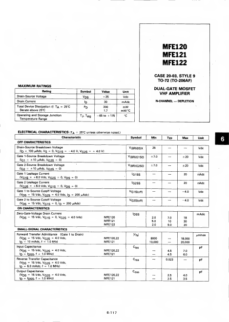
MAXIMUM RATINGS
Rating
Drain-Source Voltage
Drain Current
@Total Device Dissipation T^ = 25°C
Derate above 25°C
Operating and Storage Junction Temperature Range
Symbol v Ds id
Pd
TJ' Tstg
Value + 25 30 300
-65 to +175
Unit
Vdc m Adc m W m W/°C
°C
MFE120 MFE121 MFE122
CASE 20-03, STYLE 9
TO-72 (TO-206AF)
DUAL-GATE MOSFET VHF AMPLIFIER
- N-CHANNEL DEPLETION
ELECTRICAL CHARACTERISTICS (TA = 25°C unless otherwise noted.
Characteristic
OFF CHARACTERISTICS
Drain-Source Breakdown Voltage (ID = 100 jt Adc, Vs = 0, Vqis = -4.0 V, Vq2S = + 4.0 V)
Gate 1 -Source Breakdown Voltage
G(I 1
=
±10/i Adc, VG 2S
=
0)
Gate 2-Source Breakdown Voltage G2(l = ±10n Adc, VG 2S = 0)
Gate 1 Leakage Current
(VG1S = + 60 Vdc, VG2S = 0- VDS = 0)
Gate 2 Leakage Current
(VG2S = +6.0 Vdc, VG 1S = 0. Vqs = 0)
Gate 1 to Source Cutpff Voltage
(V DS = 15 Vdc, VQ2S = 40 vdc, Id = 200 MAdc)
Gate 2 to Source Cutoff Voltage
(Vds = 15 Vdc, Vqis = 0, Id = 200 ,i Adc) ON CHARACTERISTICS...