MHW927A Datasheet Text
MOTOROLA
The RF Line
SEMICONDUCTOR TECHNICAL DATA
Order this document by MHW927A/D
UHF Linear Power Amplifiers
Designed specifically for the United States digital 3.0 W, mobile radio. The MHW927A / B are capable of wide power range control, operate from a 12.5 V supply and require 1.0 mW of RF input power.
- MHW927A Operates from a 9.5 Volt Bias Supply (VB) MHW927B Operates from a 8.0 Volt Bias Supply (VB)
- Specified 12.5 Volt Characteristics for MHW927A/B: RF Input Power
- 1.0 mW (0 dBm) Max RF Output Power
- 6.0 W Power Gain
- 40 dB Typ Harmonics
- - 30 dBc Max @ 2 f0
- Linearity (IMD)
- - 29 dBc Max for 3rd Order;
- 34 dBc Max for 5th Order
- New Biasing and Control Techniques Providing Dynamic Range and Control Circuit Bandwidth Ideal for USDC
- 50 Ω Input / Output Impedances
- Guaranteed Stability and Ruggedness
MHW927A- MHW927B
- Motorola Preferred Device
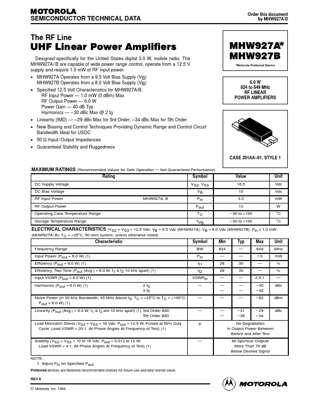
6.0 W 824 to 849 MHz RF LINEAR POWER AMPLIFIERS
CASE 301AA- 01, STYLE 1
MAXIMUM RATINGS (Remended Values for Safe Operation
- Not Guaranteed Performance)
Rating DC Supply Voltage DC Bias Voltage RF Input Power RF Output Power Operating Case Temperature Range Storage Temperature Range MHW927A, B Symbol VS2, VS3 VB Pin Pout TC Tstg Value 16.5 10 3.0 13
- 30 to +100
- 30 to +100 Unit Vdc Vdc mW W °C °C
ELECTRICAL CHARACTERISTICS (VS2 = VS3 = 12.5 Vdc; VB = 9.5 Vdc (MHW927A); VB = 8.0 Vdc (MHW927B); Pin ≤ 1.0 mW (MHW927A / B); TC = +25°C, 50 ohm system, unless otherwise noted)
Characteristic Frequency Range Input Power (Pout = 6.0 W) (1) Efficiency (Pout = 6.0 W) (1) Efficiency, Two Tone (Pout (Avg.) = 6.0 W; f1 & f2 10 kHz apart) (1) Input VSWR (Pout = 6.0 W) (1) Harmonics (Pout = 6.0 W) (1) 2 f0 3 f0 Symbol BW Pin η1 η2 VSWRin
- - ...