Datasheet4U Logo Datasheet4U.com

MRFIC1502 - 
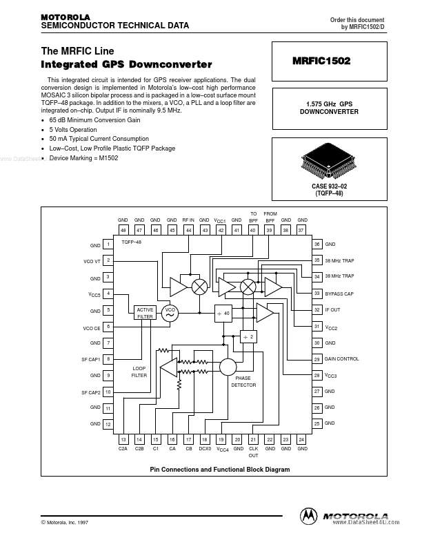
1.575 GHz GPS DOWNCONVERTER

Features

  • ly 1.0 pF; that can be achieved using either a discrete element or a microstrip open circuited stub. The evaluation circuit shown uses a 0.4 pF capacitor. Phase.
  • locked Loop Design The VCO signal at 1527.68 MHz is divided by 40 to get the second LO frequency of 38.19 MHz. In addition to providing the LO to the second mixer, the 38 MHz signal is output through a translator and is used as the sampling clock for the digital correlator and decimator circuits. There is an ad.

📥 Download Datasheet

Other Datasheets by Motorola

Full PDF Text Transcription

Click to expand full text
MOTOROLA SEMICONDUCTOR TECHNICAL DATA Order this document by MRFIC1502/D The MRFIC Line Integrated GPS Downconverter This integrated circuit is intended for GPS receiver applications. The dual conversion design is implemented in Motorola’s low–cost high performance MOSAIC 3 silicon bipolar process and is packaged in a low–cost surface mount TQFP–48 package. In addition to the mixers, a VCO, a PLL and a loop filter are integrated on–chip. Output IF is nominally 9.5 MHz. • 65 dB Minimum Conversion Gain • 5 Volts Operation • 50 mA Typical Current Consumption • Low–Cost, Low Profile Plastic TQFP Package • Device Marking = M1502 www.DataSheet4U.com MRFIC1502 1.
Published: |