Datasheet4U Logo Datasheet4U.com

MRFIC1884 Datasheet Dual Band CDMA Upconverter

Manufacturer: Motorola Semiconductor (now NXP Semiconductors)

Overview: Order this document by MRFIC1884PP/D Product Preview Dual-Band CDMA Upconverter 
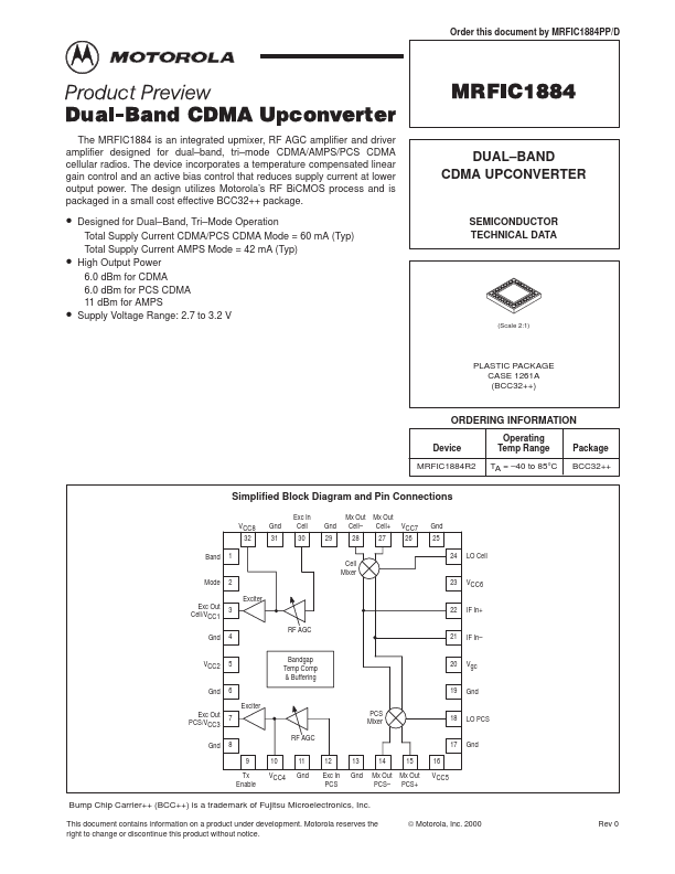
The MRFIC1884 is an integrated upmixer, RF AGC amplifier and driver amplifier designed for dual–band, tri–mode CDMA/AMPS/PCS CDMA cellular radios. The device incorporates a temperature compensated linear gain control and an active bias control that reduces supply current at lower output power. The design utilizes Motorola’s RF BiCMOS process and is packaged in a small cost effective BCC32++ package. MRFIC1884 DUAL–BAND CDMA UPCONVERTER • • • Designed for Dual–Band, Tri–Mode Operation Total Supply Current CDMA/PCS CDMA Mode = 60 mA (Typ) Total Supply Current AMPS Mode = 42 mA (Typ) High Output Power 6.0 dBm for CDMA 6.0 dBm for PCS CDMA 11 dBm for AMPS Supply Voltage Range: 2.7 to 3.2 V SEMICONDUCTOR TECHNICAL DATA (Scale 2:1) PLASTIC PACKAGE CASE 1261A (BCC32++) ORDERING INFORMATION Device MRFIC1884R2 Operating Temp Range TA = –40 to 85°C Package BCC32++ Simplified Block Diagram and Pin Connections VCC8 32 Band 1 Cell Mixer Mode Exc Out Cell/VCC1 Gnd 2 Exciter 3 RF AGC 4 Bandgap Temp Comp & Buffering 21 IF In– 22 IF In+ 23 VCC6 Gnd 31 Exc In Cell 30 Gnd 29 Mx Out Mx Out Cell– Cell+ 28 27 VCC7 26 Gnd 25 24 LO Cell VCC2 Gnd Exc Out PCS/VCC3 Gnd 5 20 Vgc Gnd 6 Exciter 7 RF AGC 9 Tx Enable 10 VCC4 11 Gnd 12 Exc In PCS 13 Gnd 14 15 16 VCC5 PCS Mixer 19 18 LO PCS Gnd 8 17 Mx Out Mx Out PCS– PCS+ Bump Chip Carrier++ (BCC++) is a trademark of Fujitsu Microelectronics, Inc. This document contains information on a product under development. Motorola reserves the right to change or discontinue this product without notice. © Motorola, Inc.

General Description

Pin 1 2 3 Function Band Mode Exciter Out (Cellular)/ VCC1 Gnd VCC2 Gnd Exciter Out (PCS)/ VCC3 Gnd Tx Enable Description Band Selection pin.

A logic ”High” (>2.4 V) selects PCS band and ”Low” (<0.4 V) selects Cellular band.

Mo