Datasheet4U Logo Datasheet4U.com

SG3525AN - PULSE WIDTH MODULATOR

Download the SG3525AN datasheet PDF. This datasheet also covers the SG3525A variant, as both devices belong to the same pulse width modulator family and are provided as variant models within a single manufacturer datasheet.

Key Features

  • NOR logic resulting in a low output for an off.
  • state while the SG3527A utilized OR logic which gives a high output when off.
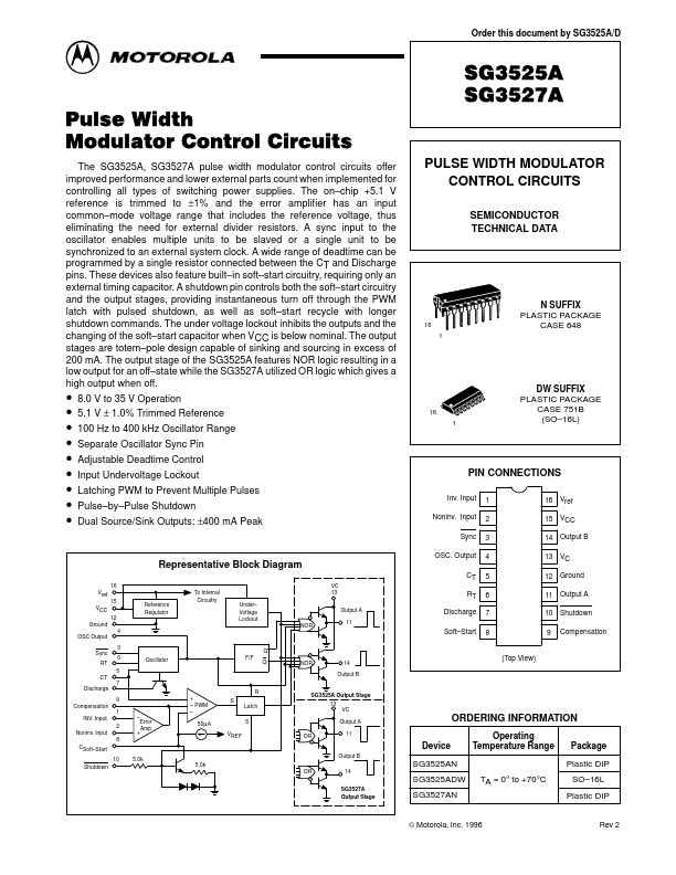
  • 8.0 V to 35 V Operation.
  • 5.1 V ± 1.0% Trimmed Reference.
  • 100 Hz to 400 kHz Oscillator Range.
  • Separate Oscillator Sync Pin.
  • Adjustable Deadtime Control.
  • Input Undervoltage Lockout.
  • Latching PWM to Prevent Multiple Pulses.
  • Pulse.
  • by.
  • Pulse Shutdown.
  • Dual Source/Sink Output.

📥 Download Datasheet

Note: The manufacturer provides a single datasheet file (SG3525A_MotorolaInc.pdf) that lists specifications for multiple related part numbers.

Full PDF Text Transcription (Reference)

The following content is an automatically extracted verbatim text from the original manufacturer datasheet and is provided for reference purposes only.

View original datasheet text
Order this document by SG3525A/D Pulse Width Modulator Control Circuits The SG3525A, SG3527A pulse width modulator control circuits offer improved performance and lower external parts count when implemented for controlling all types of switching power supplies. The on–chip +5.1 V reference is trimmed to ±1% and the error amplifier has an input common–mode voltage range that includes the reference voltage, thus eliminating the need for external divider resistors. A sync input to the oscillator enables multiple units to be slaved or a single unit to be synchronized to an external system clock. A wide range of deadtime can be programmed by a single resistor connected between the CT and Discharge pins.