Motorola SN54LS113A
The SN54 / 74LS113A offers individual J, K, set, and clock inputs. These monolithic dual flip-flops are designed so that when the clock goes HIGH, the inputs are enabled and data will be accepted. The logic level of the J and K inputs may be allowed to change when the clock pulse is HIGH and the bistable will perform according to the truth table as long as minimum setup times are observed.| Part No. | SN54LS113A |
|---|---|
| Datasheet | SN54LS113A Download |
| Manufacturer |  Motorola |
| Description | DUAL JK NEGATIVE EDGE-TRIGGERED FLIP-FLOP |
| Buy | Stock & Price |
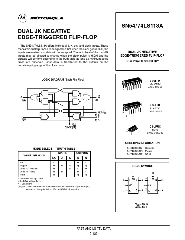
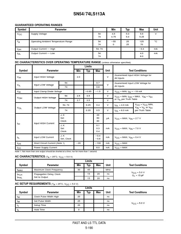
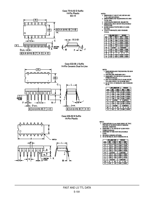
SN54/74LS113A DUAL JK NEGATIVE EDGE-TRIGGERED FLIP-FLOP Input data is transferred to the outputs on the negative-going edge of the clock pulse. DUAL JK NEGATIVE EDGE-TRIGGERED FLIP-FLOP LOW POWER SCHOTTKY LOGIC DIAGRAM (Each Flip-Flop) J SUFFIX CERAMIC CASE 632-08 14 1 Q 5(9) 6(8) Q SET (SD) 4(10) J 3(11) 1(13) CLOCK (CP) K 2(12) 14 1 N SUFFIX PLASTIC CASE 646-06 14 1 D SUFFIX SOIC CASE 751A-02 ORDERING INFORMATION MODE SELECT — TRUTH TABLE INPUTS OPERATING MODE SD Set Toggle Load “0” (Reset) Load “1” (Set) Hold L H H H H J X h l h l K X h h l l Q H q L H q Q L q H L q 3 J CP OUTPUTS SN54LSXXXJ SN74LSXXXN SN74LSXXXD Ceramic Plastic SOIC LOGIC SYMBOL 4 10 H, h = HIGH Voltage Level L, I = LOW Voltage Level X = Don’t Care l, h (q) = Lower case letters indicate the state of the referenced input (or output) l, h (q) = one set-up time prior to the HIGH to LOW clock transition. SD Q 5 11 J SD Q 9 1 2 13 Q 6 12 CP Q 8 K K VCC = PIN 14 GND = PIN 7 FAST AND LS TTL DATA 5-189 SN54/74LS113A GUARAN...