SN74LS323 Overview
Key Specifications
Package: SOIC
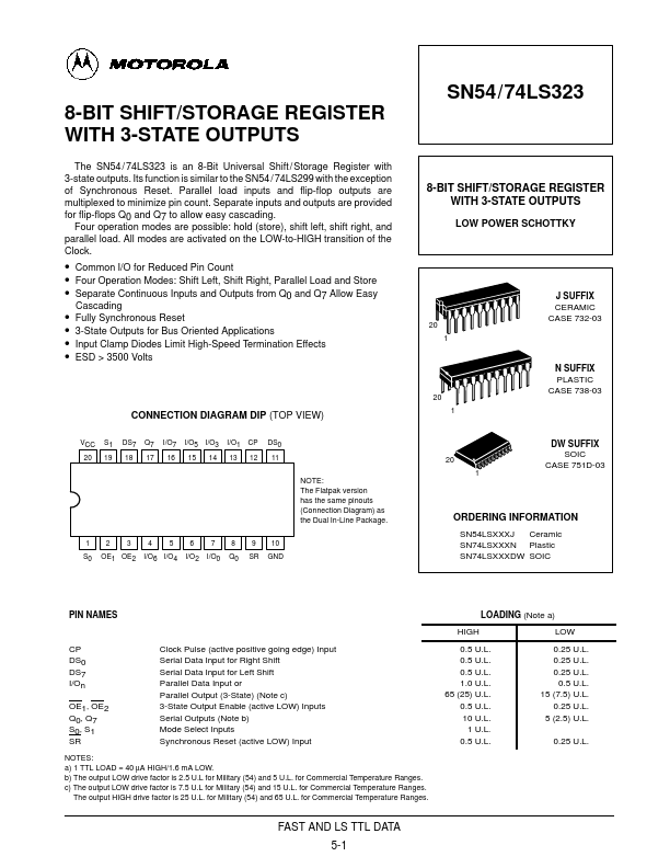
Logic Function: Shift Register
Key Features
- Common I/O for Reduced Pin Count
- Four Operation Modes: Shift Left, Shift Right, Parallel Load and Store
| Part | SN74LS323 |
|---|---|
| Description | 8-BIT SHIFT/STORAGE REGISTER |
| Manufacturer | Motorola Semiconductor |
| Size | 137.59 KB |
Package: SOIC
Logic Function: Shift Register
| Seller | Inventory | Price Breaks | Buy |
|---|---|---|---|
| Rochester Electronics | 6000 | 100+ : 1.56 USD 500+ : 1.4 USD 1000+ : 1.29 USD 10000+ : 1.15 USD |
View Offer |
| Verical | 6000 | 193+ : 1.95 USD 500+ : 1.75 USD 1000+ : 1.6125 USD 10000+ : 1.4375 USD |
View Offer |
| Part Number | Manufacturer | Description |
|---|---|---|
| SN74LS32 | onsemi | Quad 2-Input OR Gate |
| SN74LS32 | Texas Instruments | Quadruple 2-Input Positive-OR Gates |
| SN74LS320 | Texas Instruments | CRYSTAL-CONTROLLED OSCILLATORS |
| SN74LS321 | Texas Instruments | CRYSTAL-CONTROLLED OSCILLATORS |