Motorola TPV597
UHF LINEAR POWER TRANSISTOR
| Part No. | TPV597 |
|---|---|
| Datasheet | TPV597 Download |
| Manufacturer |  Motorola |
| Description | UHF LINEAR POWER TRANSISTOR |
| Buy | Stock & Price |
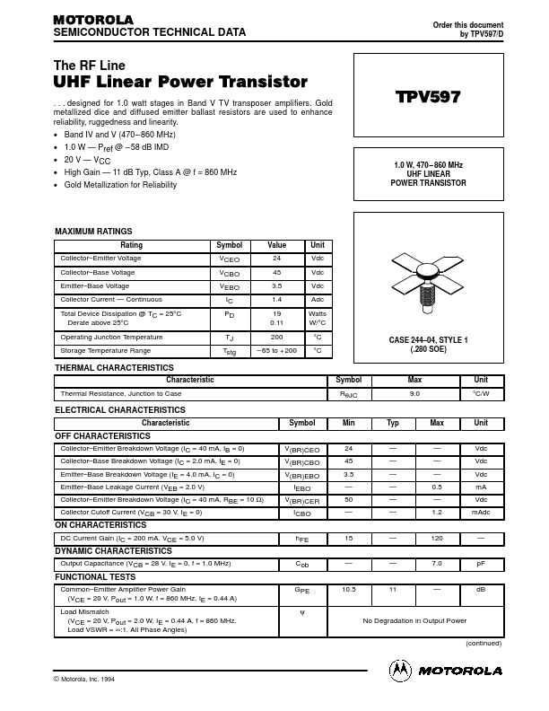
MAXIMUM RATINGS
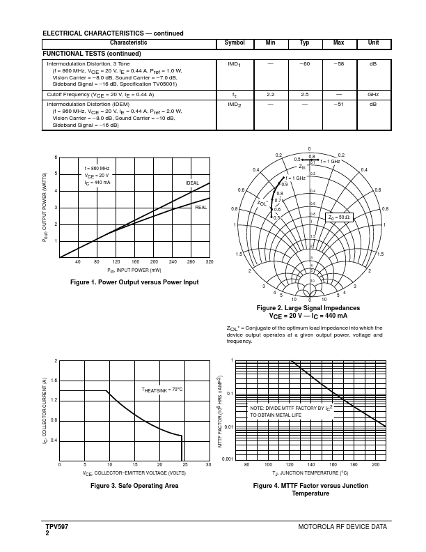
Rating Collector–Emitter Voltage Collector–Base Voltage Emitter–Base Voltage Collector Current — Continuous Total Device Dissipation @ TC = 25°C Derate above 25°C Operating Junction Temperature Storage Temperature Range Symbol VCEO VCBO VEBO IC PD TJ Tstg Value 24 45 3.5 1.4 19 0.11 200 – 65 to + 200 Unit Vdc Vdc Vdc Adc Watts W/°C °C °C CASE 244–04, STYLE 1 (.280 SOE) THERMAL CHARACTERISTICS Characteristic Thermal Resistance, Junction to Case Symbol RθJC Max 9.0 Unit °C/WELECTRICAL CHARACTERISTICS
Characteristic Symbol Min Typ Max Unit OFF CHARACTERISTICS Collector–Emitter Breakdown Voltage (IC = 40 mA, IB = 0) Collector–Base Breakdown Voltage (IC = 2.0 mA, IE = 0) Emitter–Base Breakdown Voltage (IE = 4.0 mA, IC = 0) Emitter–Base Leakage Current (VEB = 2.0 V) Collector–Emitter Breakdown Voltage (IC = 40 mA, RBE = 10 Ω) Collector Cutoff Current (VCB = 30 V, IE = 0) V(BR)CEO V(BR)CBO V(BR)EBO IEBO V(BR)CER ICBO hFE Cob GPE ψ No Degradation in Output Power (continued) 24...