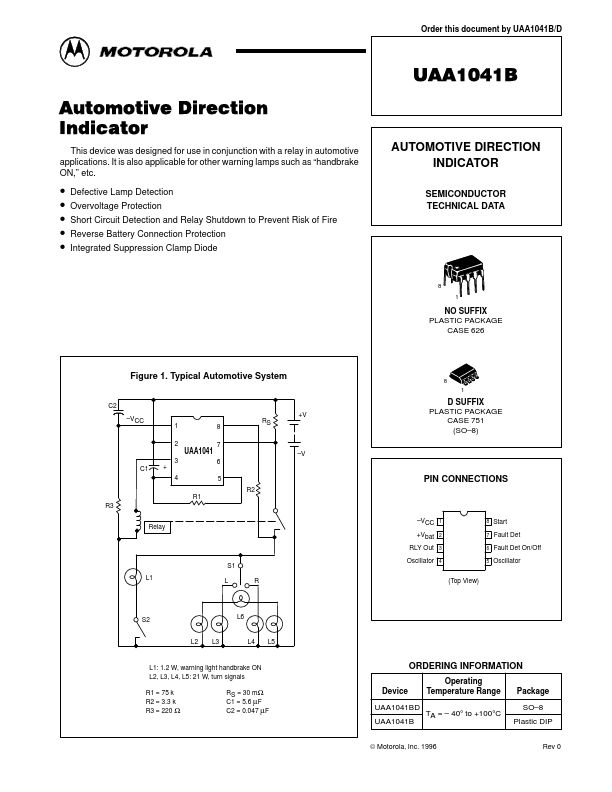
Datasheet4U Logo Datasheet4U.com

UAA1041B - AUTOMOTIVE DIRECTION INDICATOR

General Description

The circuit is designed to drive the direction indicator flasher relay.

Figure 2 shows the typical system configuration with the external components.

Key Features

  • overvoltage, defective lamp and short circuit detection. The lightbulbs L2, L3, L4, L5 are the turn signal indicators with the dashboard.
  • light L6. When switch S1 is closed, after a time delay of t1 (in our example t1 = 75 ms), the relay will be actuated. The corresponding lightbulbs (L2, L3 or L4, L5) will flash at the oscillator frequency, independent of the battery voltage of 8.0 V to 18 V. The flashing cycle stops and the circuit is reset to the initial position when switch S1 is open.

📥 Download Datasheet

Full PDF Text Transcription (Reference)

The following content is an automatically extracted verbatim text from the original manufacturer datasheet and is provided for reference purposes only.

View original datasheet text
Order this document by UAA1041B/D UAA1041B Automotive Direction Indicator This device was designed for use in conjunction with a relay in automotive applications. It is also applicable for other warning lamps such as “handbrake ON,” etc. AUTOMOTIVE DIRECTION INDICATOR SEMICONDUCTOR TECHNICAL DATA • • • • • Defective Lamp Detection Overvoltage Protection Short Circuit Detection and Relay Shutdown to Prevent Risk of Fire Reverse Battery Connection Protection Integrated Suppression Clamp Diode 8 1 NO SUFFIX PLASTIC PACKAGE CASE 626 Figure 1.