NXP Semiconductors 74F113
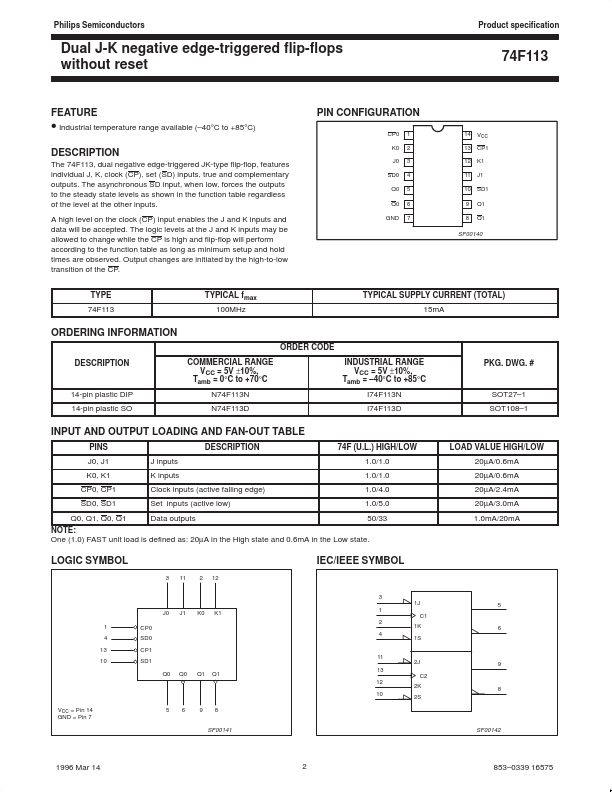
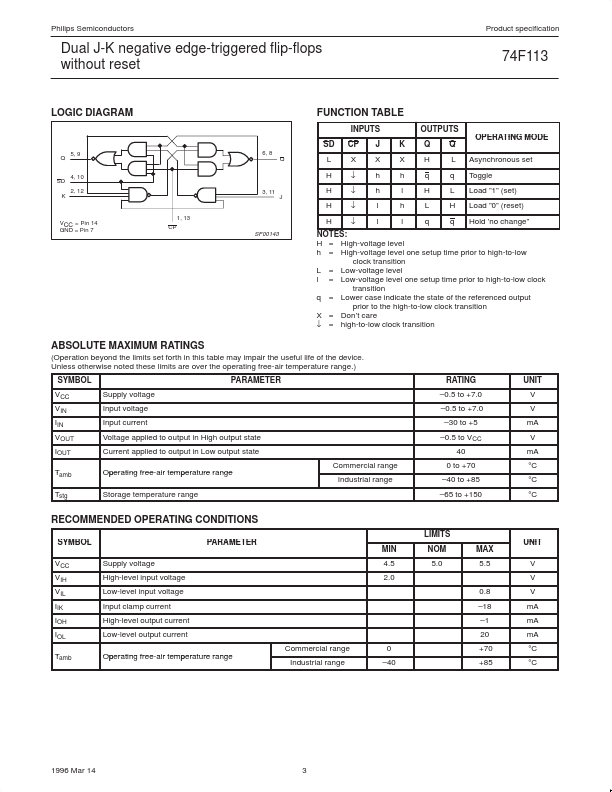
The 74F113, dual negative edge-triggered JK-type flip-flop, features individual J, K, clock (CP), set (SD) inputs, true and complementary outputs. The asynchronous SD input, when low, forces the outputs to the steady state levels as shown in the function table regardless of the level at the other inputs. The logic levels at the J and K inputs may be allowed to change while the CP is high and flip-flop will perform according to the function table as long as minimum setup and hold times are observed.
| Part No. |
74F113 |
| Datasheet |
74F113
Download
|
| Manufacturer |
 NXP Semiconductors |
| Description |
Dual J-K negative edge-triggered flip-flops |
| Buy |
Stock & Price
|
DESCRIPTION
A high level on the clock (CP) input enables the J and K inputs and data will be accepted. Output changes are initiated by the high-to-low transition of the CP. TYPE 74F113 TYPICAL fmax 100MHz PIN CONFIGURATION CP0 K0 J0 SD0 Q0 Q0 GND 1 2 3 4 5 6 7 14 13 12 11 10 9 8 VCC CP1 K1 J1 SD1 Q1 Q1 SF00140 TYPICAL SUPPLY CURRENT (TOTAL) 15mA ORDERING INFORMATION ORDER CODE DESCRIPTION
COMMERCIAL RANGE VCC = 5V ±10%, Tamb = 0°C to +70°C N74F113N N74F113D INDUSTRIAL RANGE VCC = 5V ±10%, Tamb = –40°C to +85°C I74F113N I74F113D PKG. DWG. # 14-pin plastic DIP 14-pin plastic SO SOT27–1 SOT108–1 INPUT AND OUTPUT LOADING AND FAN-OUT TABLE PINS J0, J1 K0, K1 CP0, CP1 SD0, SD1 Q0, Q1, Q0, Q1 J inputs K inputs Clock inputs (active falling edge) Set inputs (active low) Data outputs DESCRIPTION
74F (U.L.) HIGH/LOW 1.0/1.0 1.0/1.0 1.0/4.0 1.0/5.0 50/33 LOAD VALUE HIGH/LOW 20µA/0.6mA 20µA/0.6mA 20µA/2.4mA 20µA/3.0mA 1.0mA/20mA NOTE: One (1.0) FAST unit load is defined as: 20µA in the High state and 0.6mA in the Low state.