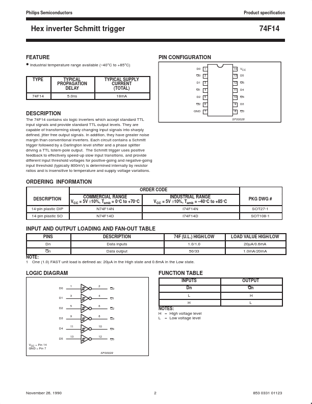
DESCRIPTION
In addition, they have greater noise margin than conventional inverters. The Schmitt trigger uses positive feedback to effectively speed-up slow input transitions, and provide different input threshold voltages for positive-going and negative-going input threshold (typically 800mV) is determined internally by resistor ratios and is insensitive to temperature and supply voltage variations. GND SF00028 ORDERING INFORMATION ORDER CODE DESCRIPTION
14-pin plastic DIP 14-pin plastic SO COMMERCIAL RANGE VCC = 5V ±10%, Tamb = 0°C to +70°C N74F14N N74F14D INDUSTRIAL RANGE VCC = 5V ±10%, Tamb = –40°C to +85°C I74F14N I74F14D PKG DWG # SOT27-1 SOT108-1 INPUT AND OUTPUT LOADING AND FAN-OUT TABLE PINS Dn Qn DESCRIPTION
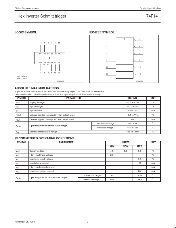
Data inputs Data output 74F (U.L.) HIGH/LOW 1.0/1.0 50/33 LOAD VALUE HIGH/LOW 20µA/0.6mA 1.0mA/20mA NOTE: 1 One (1.0) FAST unit load is defined as: 20µA in the High state and 0.6mA in the Low state. LOGIC DIAGRAM D0 D1 D2 D3 D4 D5 VCC = Pin 14 GND = Pin 7 1 3 5 9 11 13 2... NXP Semiconductors