NXP Semiconductors 74HC4510
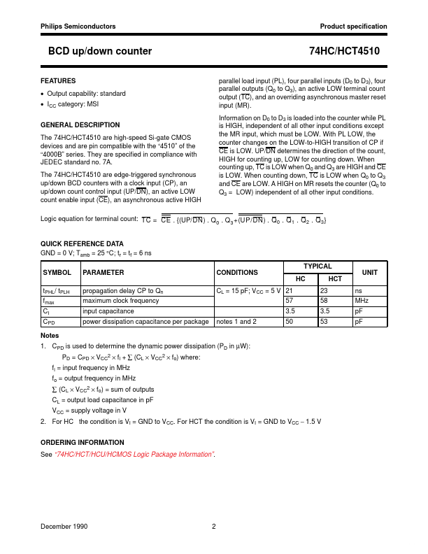
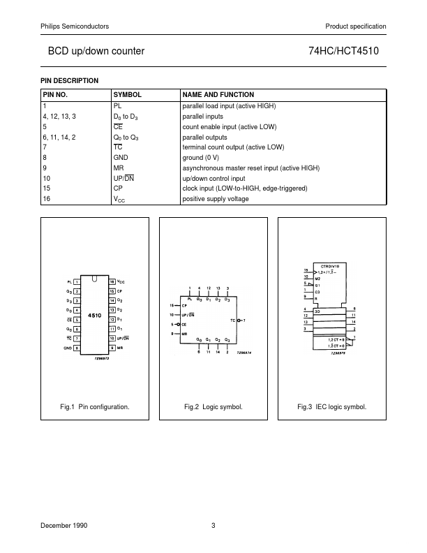
The 74HC/HCT4510 are high-speed Si-gate CMOS devices and are pin compatible with the “4510” of the “4000B” series. They are specified in compliance with JEDEC standard no. The 74HC/HCT4510 are edge-triggered synchronous up/down BCD counters with a clock input (CP), an up/down count control input (UP/DN), an active LOW count enable input (CE), an asynchronous active HIGH 74HC/HCT4510 parallel load input (PL), four parallel inputs (D0 to D3), four parallel outputs (Q0 to Q3), an active LOW terminal count output (TC), and an overriding asynchronous master reset input (MR).| Part No. | 74HC4510 |
|---|---|
| Datasheet | 74HC4510 Download |
| Manufacturer |  NXP Semiconductors |
| Description | BCD up/down counter |
| Buy | Stock & Price |

FEATURES
● Output capability: standard● ICC category: MSI
GENERAL DESCRIPTION
7A. Information on D0 to D3 is loaded into the counter while PL is HIGH, independent of all other input conditions except the MR input, which must be LOW. With PL LOW, the counter changes on the LOW-to-HIGH transition of CP if CE is LOW. UP/DN determines the direction of the count, HIGH for counting up, LOW for counting down. When counting up, TC is LOW when Q0 and Q3 are HIGH and CE is LOW. When counting down, TC is LOW when Q0 to Q3 and CE are LOW. A HIGH on MR resets the counter (Q0 to Q3 = LOW) independent of all other input conditions. Logic equation for terminal count: TC = CE . {(UP/DN) . Q . Q +(UP/DN) . Q 0 . Q 1 . Q 2 . Q 3 } 0 3 QUICK REFERENCE DATA GND = 0 V; Tamb = 25 °C; tr = tf = 6 ns TYPICAL SYMBOL tPHL/ tPLH fmax CI CPD Notes 1. CPD is used to determine the dynamic power dissipation (PD in µW): PD = CPD × VCC2 × fi + ∑ (CL × VCC2 × fo) where: fi = input frequency in MHz fo = output frequency in MHz ∑ (CL × VCC2 × fo) = sum of outputs CL = output load capacitance in pF VCC = supply voltage in V 2.