NXP Semiconductors A2I09VD015GNR1
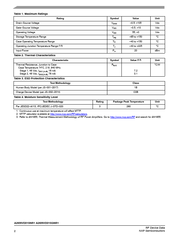
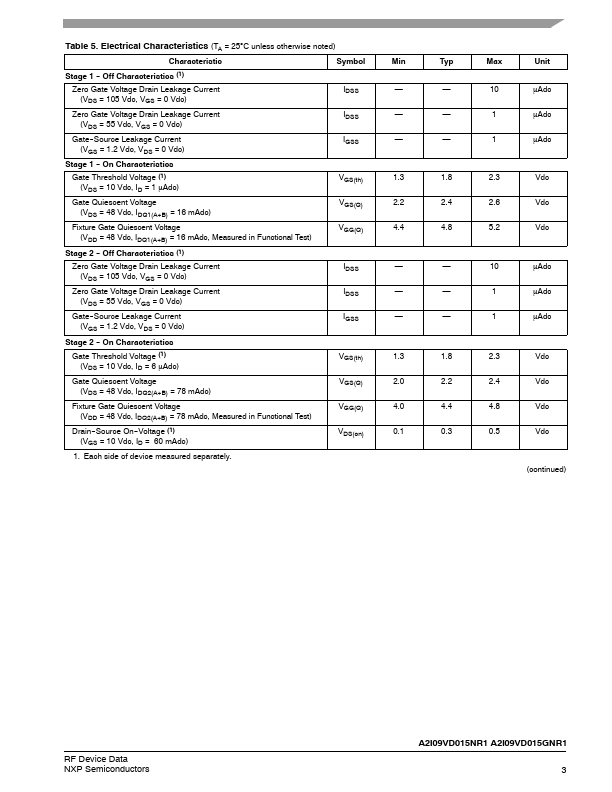
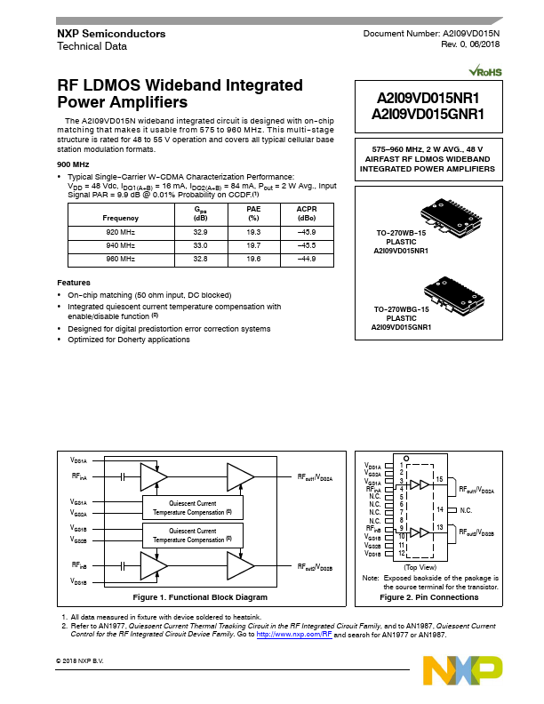
The A2I09VD015N wideband integrated circuit is designed with on--chip matching that makes it usable from 575 to 960 MHz. This multi -- stage structure is rated for 48 to 55 V operation and covers all typical cellular base station modulation formats.| Part No. | A2I09VD015GNR1 |
|---|---|
| Datasheet | A2I09VD015GNR1 Download |
| Manufacturer |  NXP Semiconductors |
| Description | Power Amplifiers |
| Buy | Stock & Price |
FEATURES
● On--chip matching (50 ohm input, DC blocked)● Integrated quiescent current temperature compensation with enable/disable function (2)
● Designed for digital predistortion error correction systems
● Optimized for Doherty applications A2I09VD015NR1 A2I09VD015GNR1 575–960 MHz, 2 W AVG., 48 V AIRFAST RF LDMOS WIDEBAND INTEGRATED POWER AMPLIFIERS TO--270WB--15 PLASTIC A2I09VD015NR1 TO--270WBG--15 PLASTIC A2I09VD015GNR1 VDS1A RFinA VGS1A VGS2A VGS1B VGS2B RFinB VDS1B Quiescent Current Temperature Compensation (2) Quiescent Current Temperature Compensation (2) Figure 1. Functional Block Diagram RFout1/VDS2A RFout2/VDS2B VDS1A 1 VGS2A 2 VGS1A 3 RFinA 4 N.C. 5 N.C. 6 N.C. 7 N.C. 8 RFinB 9 VGS1B 10 VGS2B 11 VDS1B 12 15 RFout1/VDS2A 14 N.C. 13 RFout2/VDS2B (Top View) Note: Exposed backside of the package is the source terminal for the transistor. Figure 2. Pin Connections 1. All data measured in fixture with device soldered to heatsink. 2. Refer to AN1977, Quiescent Current Thermal Tracking Circuit in the RF Integrated Circuit Family, and to AN1987, Quiescent Current Control for the RF Integrated Circuit Device Family.