DESCRIPTION
N-P-N silicon planar epitaxial transistor intended for transmitting applications in class-A, B or C in the u.h.f. and v.h.f. range for a nominal supply voltages up to 13,5 V. Product specification BLW81 QUICK REFERENCE DATA R.F. performance up to Th = 25 °C in an unneutralized common-emitter class-B circuit MODE OF OPERATION VCE V f MHz PL W Gp dB η % c.w. 12,5 470 10 > 6,0 > 60 c.w. 12,5 175 10 typ. 13,5 typ. 60 zi Ω 1,3 + j2,5 1,2 − j0,6 YL mS 150 − j66 140 − j80 PIN CONFIGURATION handbook, halfpage 4 1 3 PINNING - SOT122A. PIN DESCRIPTION
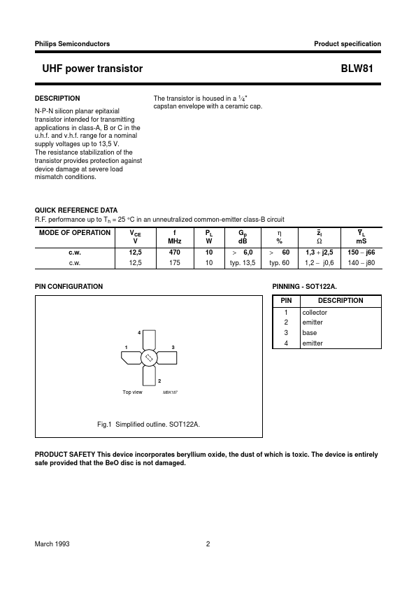
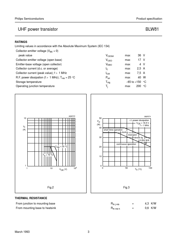
1 collector 2 emitter 3 base 4 emitter Top view 2 MBK187 Fig.1 Simplified outline. SOT122A. PRODUCT SAFETY This device incorporates beryllium oxide, the dust of which is toxic. The device is entirely safe provided that the BeO disc is not damaged. March 1993 2 Philips Semiconductors UHF power transistor RATINGS Limiting values in accordance with the Absolute Maximum System (IEC 134) Collector-emitter voltage (VBE = 0) peak value Collector-emitter voltage (open base) Emitter-base voltage (open collector) Collector current (d.c. or average) Collector current (peak value); f > 1 MHz R.F. NXP Semiconductors