BR211-260
BR211-260 is Breakover diodes manufactured by NXP Semiconductors.
Philips Semiconductors
Product specification
Breakover diodes
BR211 series
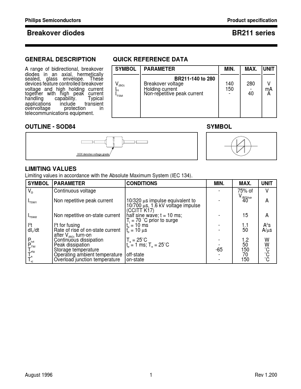
GENERAL DESCRIPTION
A range of bidirectional, breakover diodes in an axial, hermetically sealed, glass envelope. These devices feature controlled breakover voltage and high holding current together with high peak current handling capability. Typical applications include transient overvoltage protection in telemunications equipment.
QUICK REFERENCE DATA
SYMBOL V(BO) IH ITSM PARAMETER BR211-140 to 280 Breakover voltage Holding current Non-repetitive peak current MIN. 140 150 MAX. 280 40 UNIT V m A A
OUTLINE
- SOD84
BR211-XXX
SYMBOL
XXX denotes voltage grade
LIMITING VALUES
Limiting values in accordance with the Absolute Maximum System (IEC 134). SYMBOL VD ITSM1 ITSM2 I2t d IT/dt Ptot PTM Tstg Ta Tvj PARAMETER Continuous voltage Non repetitive peak current Non repetitive on-state current I2t for fusing Rate of rise of on-state current after V(BO) turn-on Continuous dissipation Peak dissipation Storage temperature Operating ambient temperature Overload junction temperature 10/320 µs impulse equivalent to 10/700 µs, 1.6 k V voltage impulse (CCITT K17) half sine wave; t = 10 ms; Tj = 70 ˚C prior to surge tp = 10 ms tp = 10 µs Ta = 25˚C tp = 1 ms; Ta = 25˚C off-state on-state CONDITIONS MIN. -65 MAX. 75% of V(BO)typ 40 15 1.1 50 1.2 50 150 70 150 UNIT V A A A2s A/µs W W ˚C ˚C ˚C
August 1996
Rev 1.200
Philips Semiconductors
Product specification
Breakover diodes
BR211 series
THERMAL RESISTANCES
SYMBOL Rth j-e Rth j-a Zth j-a Rth e-tp Rth e-a Rth tp-a PARAMETER Thermal resistance junction to envelope Thermal resistance junction to ambient Thermal impedance junction to ambient Thermal resistance envelope to tie point Thermal resistance envelope to ambient Thermal resistance tie point to ambient CONDITIONS MIN. mounted as fig:12 tp = 1 ms lead length = 5 mm lead length = 10 mm lead length = 5 mm lead length = 10 mm mounted as fig:12 mounted with 1 cm2 copper laminate per lead....