NXP Semiconductors BT131
The rate of rise of current should not exceed 3 A/ s.| Part No. | BT131 |
|---|---|
| Datasheet | BT131 Download |
| Manufacturer |  NXP Semiconductors |
| Description | Triacs |
| Buy | Stock & Price |
FEATURES AND BENEFITS
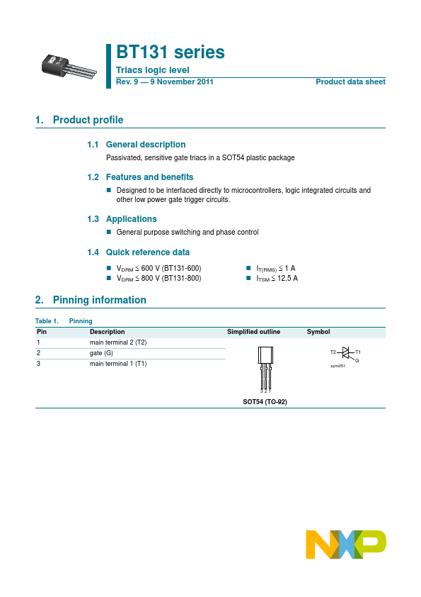
● Designed to be interfaced directly to microcontrollers, logic integrated circuits and other low power gate trigger circuits. 1.3APPLICATIONS
● General purpose switching and phase control 1.4 Quick reference data● VDRM 600 V (BT131-600)
● VDRM 800 V (BT131-800)
● IT(RMS) 1 A
● ITSM 12.5 A 2. Pinning information Table 1. Pin 1 2 3 Pinning
DESCRIPTION
main terminal 2 (T2) gate (G) main terminal 1 (T1) Simplified outline Symbol T2 sym051 T1 G 321 SOT54 (TO-92) NXP Semiconductors BT131 series Triacs logic level 3. Ordering information Table 2. Ordering information Type number Package NameDESCRIPTION
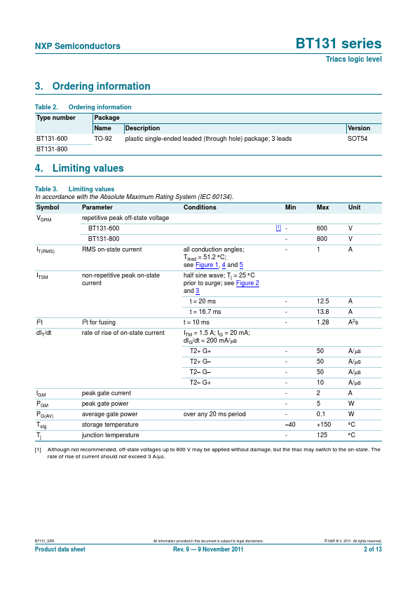
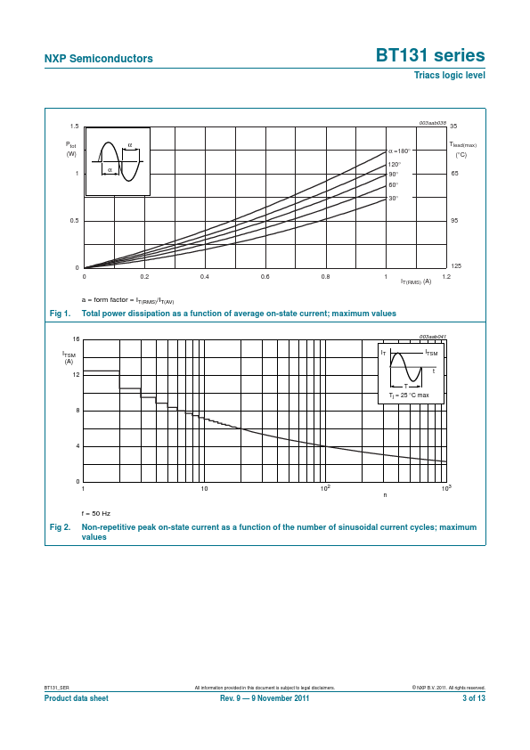
BT131-600 TO-92 plastic single-ended leaded (through hole) package; 3 leads BT131-800 4. Limiting values Version SOT54 Table 3. Limiting values In accordance with the Absolute Maximum Rating System (IEC 60134). Symbol Parameter Conditions VDRM repetitive peak off-state voltage BT131-600 BT131-800 IT(RMS) RMS on-state current all conduction angles; Tlead = 51.2...