• Part: BTA151-650R
  • Description: Thyristors sensitive gate
  • Manufacturer: NXP Semiconductors
  • Size: 43.13 KB
Download BTA151-650R Datasheet PDF
BTA151-650R page 2
Page 2
BTA151-650R page 3
Page 3

BTA151-650R Datasheet Text

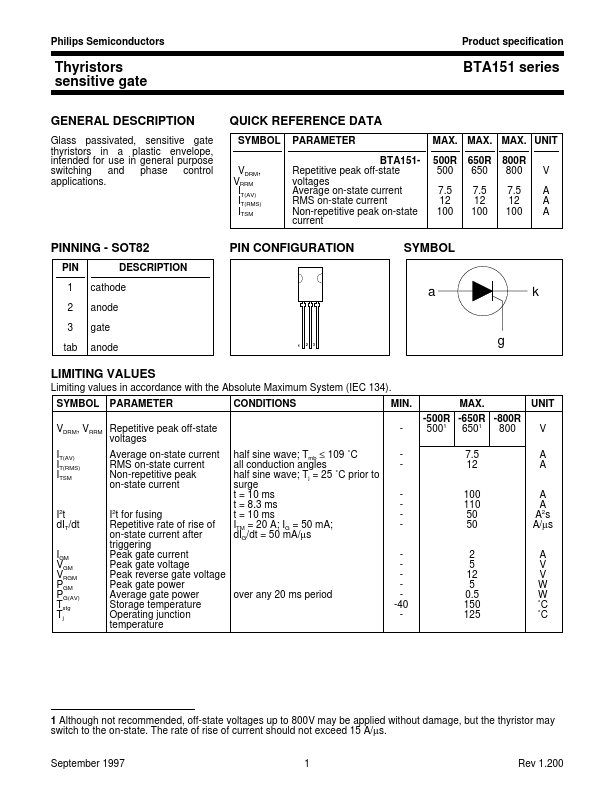
Philips Semiconductors Product specification Thyristors sensitive gate GENERAL DESCRIPTION Glass passivated, sensitive gate thyristors in a plastic envelope, intended for use in general purpose switching and phase control applications. BTA151 series QUICK REFERENCE DATA SYMBOL VDRM, VRRM IT(AV) IT(RMS) ITSM PARAMETER BTA151Repetitive peak off-state voltages Average on-state current RMS on-state current Non-repetitive peak on-state current MAX. MAX. MAX. UNIT 500R 500 7.5 12 100 650R 650 7.5 12 100 800R 800 7.5 12 100 V A A A PINNING - SOT82 PIN 1 2 3 tab DESCRIPTION cathode anode gate anode PIN CONFIGURATION SYMBOL a k 1 2 3 g LIMITING VALUES Limiting values in accordance with the Absolute Maximum System (IEC 134). SYMBOL PARAMETER CONDITIONS MIN. half sine wave; Tmb ≤ 109 ˚C all conduction angles half sine wave; Tj = 25 ˚C prior to surge t = 10 ms t = 8.3 ms t = 10 ms ITM = 20 A; IG = 50 mA; dIG/dt = 50 mA/µs -40 MAX. -500R -650R -800R 5001 6501 800 7.5 12 100 110 50 50 2 5 12 5 0.5 150 125 UNIT V A A A A A2s A/µs A V V W W ˚C ˚C VDRM, VRRM Repetitive peak off-state voltages IT(AV) IT(RMS) ITSM Average on-state current RMS on-state current Non-repetitive peak on-state current I2t dIT/dt IGM VGM VRGM PGM PG(AV) Tstg Tj I2t for fusing Repetitive rate of rise of on-state current after triggering Peak gate current Peak gate voltage Peak reverse gate voltage Peak gate power Average gate power over any 20 ms period Storage temperature Operating junction temperature 1 Although not remended, off-state voltages up to 800V may be applied without damage, but the thyristor may switch to the on-state. The rate of rise of current should not exceed 15 A/µs. September 1997 1 Rev 1.200 Philips Semiconductors Product specification Thyristors sensitive...