DESCRIPTION
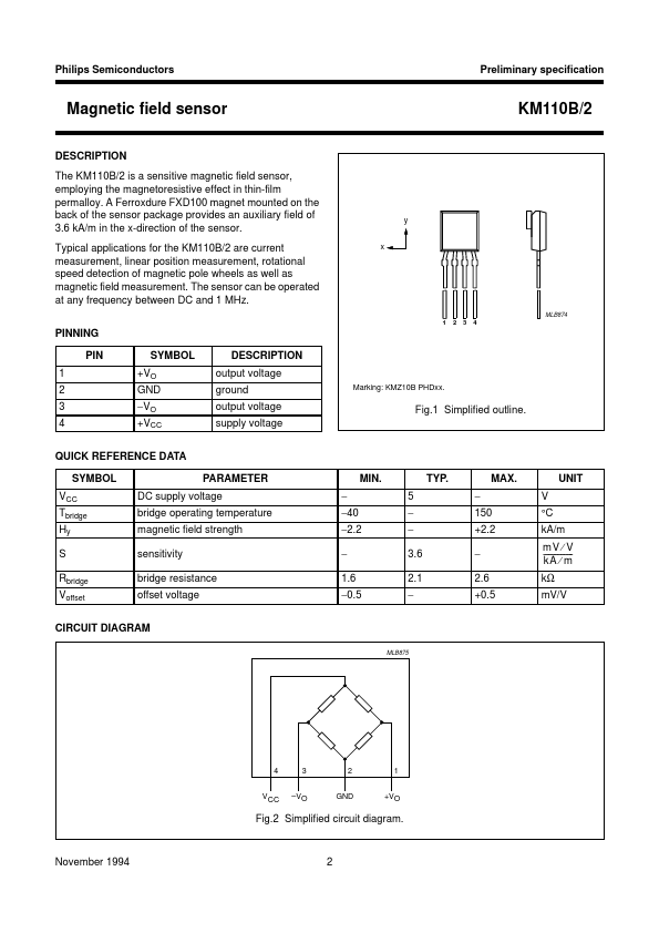
A Ferroxdure FXD100 magnet mounted on the back of the sensor package provides an auxiliary field of 3.6 kA/m in the x-direction of the sensor. Typical applications for the KM110B/2 are current measurement, linear position measurement, rotational speed detection of magnetic pole wheels as well as magnetic field measurement. PINNING PIN 1 2 3 4 SYMBOL +VO GND −VO +VCC DESCRIPTION
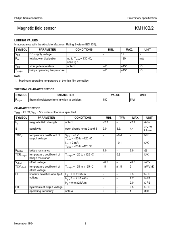
output voltage ground output voltage supply voltage Marking: KMZ10B PHDxx. x KM110B/2 y MLB874 1 2 3 4 Fig.1 Simplified outline. QUICK REFERENCE DATA SYMBOL VCC Tbridge Hy S Rbridge Voffset PARAMETER DC supply voltage bridge operating temperature magnetic field strength sensitivity bridge resistance offset voltage − −40 −2.2 − 1.6 −0.5 MIN. 5 − − 3.6 2.1 − TYP. − 150 +2.2 − 2.6 +0.5 MAX. V °C kA/m mV ⁄ V ---------------kA ⁄ m kΩ mV/V UNIT CIRCUIT DIAGRAM MLB875 handbook, full pagewidth 4 VCC 3 –VO 2 GND 1 +VO Fig.2 Simplified circuit diagram. November 1994 2 Philips Semiconductors Preliminary specification Magnetic field sensor LIMITING VALUES In accordance with the Absolute Maximum Rating System (IEC 134). NXP Semiconductors