NXP Semiconductors PDTC114EK
This data sheet contains target or goal specific| Part No. | PDTC114EK |
|---|---|
| Datasheet | PDTC114EK Download |
| Manufacturer |  NXP Semiconductors |
| Description | NPN resistor-equipped transistor |
| Buy | Stock & Price |
FEATURES
● Built-in bias resistors R1 and R2 (typ. 10 kΩ each)● Simplification of circuit design
● Reduces number of components and board space.
APPLICATIONS
● Especially suitable for space reduction in interface and driver circuits● Inverter circuit configurations without use of external resistors.
DESCRIPTION
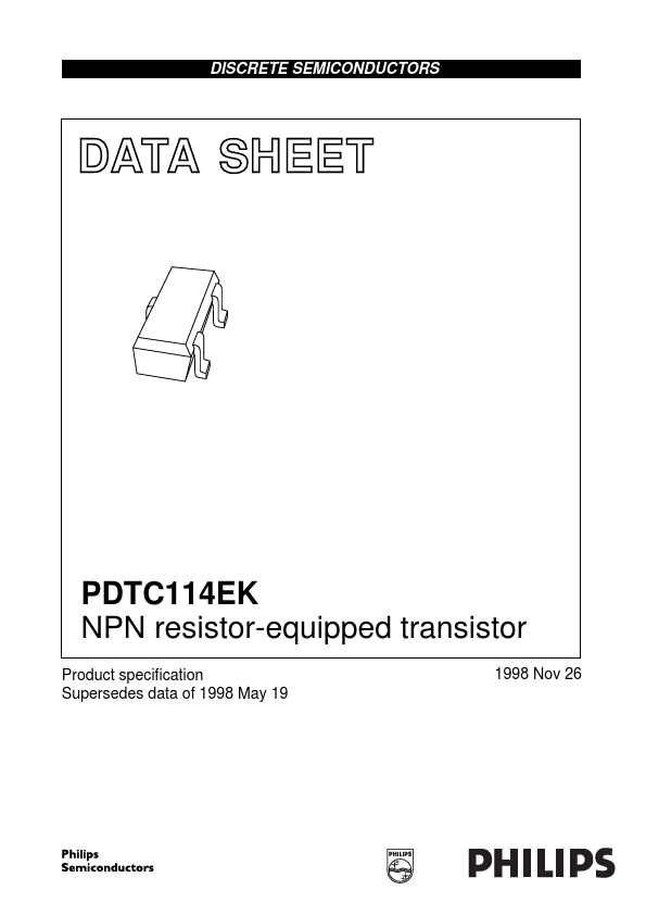
NPN resistor-equipped transistor in an SC-59 plastic package. PNP complement: PDTA114EK. 1 3 2 MGA893 - 1 PDTC114EK 3 3 R1 1 R2 2 1 Top view 2 MAM284 Fig.1 Simplified outline (SC-59) and symbol. MARKING TYPE NUMBER PDTC114EK MARKING CODE 04 PINNING PIN 1 2 3DESCRIPTION
base/input emitter/ground collector/output Fig.2 Equivalent inverter symbol. QUICK REFERENCE DATA SYMBOL VCEO IO ICM Ptot hFE R1 R2 ------R1 PARAMETER collector-emitter voltage output current (DC) peak collector current total power dissipation DC current gain input resistor resistor ratio Tamb ≤ 25 °C IC = 5 mA; VCE = 5 V CONDITIONS open base − − − − 30 7 0.8 MIN. − − − − − 10 1 TYP. MAX. 50 100 100 250 − 13 1.
