SI9956DY
SI9956DY is N-channel enhancement mode field-effect transistor manufactured by NXP Semiconductors.
Description
Dual N-channel enhancement mode field-effect transistor in a plastic package using Trench MOS™1 technology. Product availability: Si9956DY in SOT96-1 (SO8).
2. Features s Low on-state resistance s Fast switching s Trench MOS™ technology.
3. Applications s s s s s DC to DC convertors DC motor control Lithium-ion battery applications Notebook PC Portable equipment applications. c c
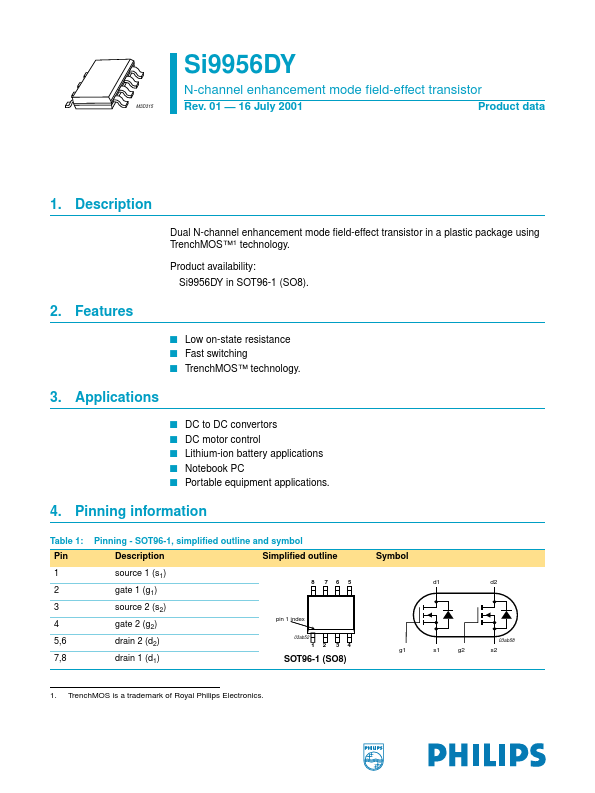
4. Pinning information
Table 1: Pin 1 2 3 4 5,6 7,8 Pinning
- SOT96-1, simplified outline and symbol Description source 1 (s1)
8 7 6 5 d1 d2
Simplified outline
Symbol gate 1 (g1) source 2 (s2) gate 2 (g2) drain 2 (d2) drain 1 (d1) pin 1 index
03ab52
03ab58 g1 s1 g2 s2
SOT96-1 (SO8)
1.
Trench MOS is a trademark of Royal Philips Electronics.
Philips Semiconductors
N-channel enhancement mode field-effect transistor
5. Quick reference data
Table 2: VDS ID Ptot Tj RDSon Quick reference data Conditions Tj = 25 to 150 °C Tamb = 25 °C; pulsed; tp ≤ 10 s Tamb = 25 °C; pulsed; tp ≤ 10 s VGS = 10 V; ID = 2.2 A VGS = 4.5 V; ID = 1 A Typ
- -
- - 55 70 Max 20 3.5 2 150 100 200 Unit V A W °C mΩ mΩ drain-source voltage (DC) drain current (DC) total power dissipation junction temperature drain-source on-state resistance Symbol Parameter
6. Limiting values
Table 3: Limiting values In accordance with the Absolute Maximum Rating System (IEC 60134). Symbol Parameter VDS VGS ID IDM Ptot Tstg Tj IS drain-source voltage (DC) gate-source voltage (DC) drain current (DC) peak drain current total power dissipation storage temperature operating junction temperature source (diode forward) current (DC) Tamb = 25 °C Tamb = 25 °C; pulsed; tp ≤ 10 s; Figure 2 and 3 Tamb = 70 °C; pulsed; tp ≤ 10 s; Figure 2 Tamb = 25 °C; pulsed; tp ≤ 10 µs; Figure 3 Tamb = 25 °C; pulsed; tp ≤ 10 s; Figure 1 Tamb = 70 °C; pulsed; tp ≤ 10 s; Figure 1 Conditions Tj = 25 to 150 °C Min
- -
- -
- -
- - 55
- 55
- Max 20 ±20 3.5 2.8 14 2 1.3 +150 +150 1.3 Unit V V A A A W W °C °C A
Source-drain...