GENERAL DESCRIPTION
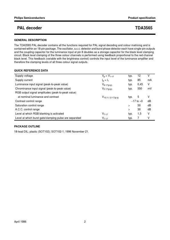
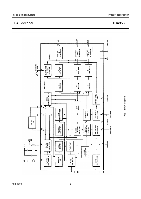
TDA3565 The oscillator, a.c.c. detector and burst phase detector each have single-pin outputs and the coupling capacitor for the luminance input at pin 8 doubles as a storage capacitor for the black level clamping circuit. Black level clamping of the three colour channels is performed using feedback proportional to the red channel black level. QUICK REFERENCE DATA Supply voltage Supply current Luminance input signal (peak-to-peak value) Chrominance input signal (peak-to-peak value) RGB output signal amplitudes (peak-to-peak value) at nominal luminance and contrast Contrast control range Saturation control range A.C.C. control range Level at which RGB blanking is activated Level at which burst gate/clamping pulse are separated PACKAGE OUTLINE 18-lead DIL; plastic (SOT102); SOT102-1; 1996 November 21. V7-17 V7-17 > > typ. typ. V10,11,12-17(p-p) typ. 5 50 30 1,5 7 V dB dB dB V V −17 to +3 Vp = V1-17 Ip = I1 V8-17(p-p) V3-17(p-p) typ. typ. typ. typ. 12 85 0,45 550 V mA V mV April 1986 2 Philips Semiconductors Product specification PAL decoder TDA3565 April 1986 3 Fig.1 Block diagram. NXP Semiconductors