National Semiconductor DM74LS952
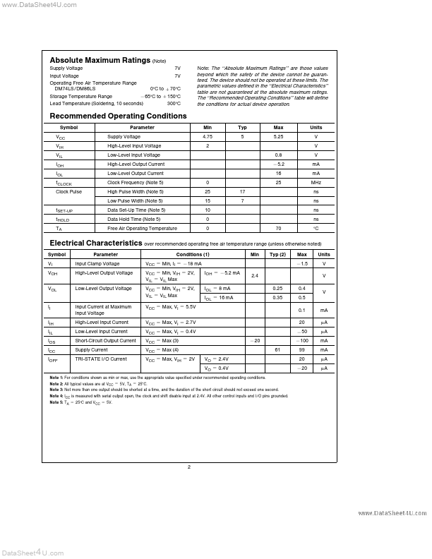
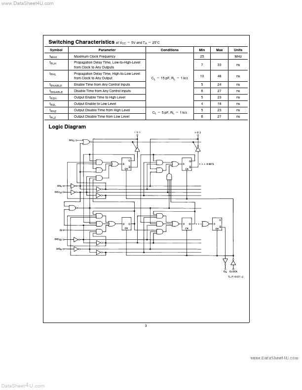
The ‘‘Absolute Maximum Ratings’’ are those values beyond which the safety of the device cannot be guaranteed The device should not be operated at these limits The parametric values defined in the ‘‘Electrical Characteristics’’ table are not guaranteed at the absolute maximum ratings The ‘‘Recommended Operating Conditions’’ table will define the conditions for actual device operation 0 C to a 70 C b 65 C to a 150 C Storage Temperature Range Lead Temperature (Soldering 10 seconds) 300 C Recommended Operating Conditions Symbol VCC VIH VIL IOH IOL fCLOCK Clock Pulse Parameter Supply Voltage...| Part No. | DM74LS952 |
|---|---|
| Datasheet | DM74LS952 Download |
| Manufacturer |  National Semiconductor |
| Description | Dual Rank 8-Bit TRI-STATE?Shift Register |
| Buy | Stock & Price |
GENERAL DESCRIPTION
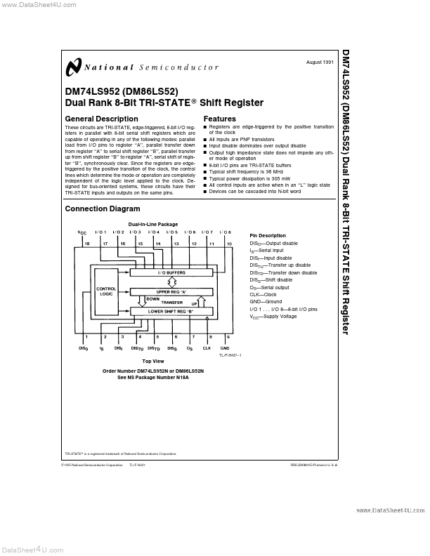
These circuits are TRI-STATE edge-triggered 8-bit I O registers in parallel with 8-bit serial shift registers which are capable of operating in any of the following modes parallel load from I O pins to register ‘‘A’’ parallel transfer down from register ‘‘A’’ to serial shift register ‘‘B’’ parallel transfer up from shift register ‘‘B’’ to register ‘‘A’’ serial shift of register ‘‘B’’ synchronously clear Since the registers are edgetriggered by the positive transition of the clock the control lines which determine the mode or operation are completely independent of the logic level applied to the clock Designed for bus-oriented systems these circuits have their TRI-STATE inputs and outputs on the same pinsFEATURES
Y Y Y Y Y Y Y Y Y Registers are edge-triggered by the positive transition of the clock All inputs are PNP transistors Input disable dominates over output disable Output high impedance state does not impede any other mode of operation 8-bit I O pins are TRI-...