LM3641
LM3641 is Lithium-Ion Battery Pack Protection Circuit manufactured by National Semiconductor.
Description
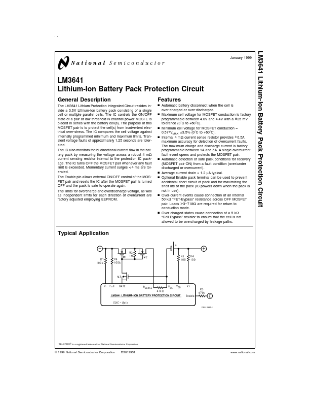
The LM3641 Lithium Protection Integrated Circuit resides inside a 3.6V Lithium-Ion battery pack consisting of a single cell or multiple parallel cells. The IC controls the ON/OFF state of a pair of low threshold N-channel power MOSFETs placed in series with the battery cell(s). The purpose of this MOSFET pair is to protect the cell(s) from inadvertent electrical over-stress. The IC pares the cell voltage against internally programmed minimum and maximum limits. Transient voltage faults of approximately 1.25 seconds are tolerated. The IC also monitors the bi-directional current flow in the battery pack by measuring the voltage across a robust 4 mΩ current sensing resistor internal to the protection IC package. The IC turns OFF the MOSFET pair whenever any fault limit is exceeded. Momentary current surges < 4 ms are tolerated. The Enable pin allows external ON/OFF control of the MOSFET pair and resets the IC after the MOSFET pair is turned OFF and the pack is safe to operate again. The limits for overcharge and overdischarge voltage, as well as independent limits for each direction of overcurrent are factory adjusted employing EEPROM.
Features n Automatic battery disconnect when the cell is over-charged or over-discharged. n Maximum cell voltage for MOSFET conduction is factory programmable between 4.0V and 4.4V with a ± 25 m V tolerance (0˚C to +60˚C). n Minimum cell voltage for MOSFET conduction = 0.57
- VMAX ± 3.5% (0˚C to +60˚C). n Internal 4 mΩ current sense resistor provides ± 0.5A maximum accuracy for detection of overcurrent faults. The maximum charge and discharge current is factory programmable between 1A and 5A. A single overcurrent fault event opens and protects the MOSFET pair. n Automatic detection of safe pack conditions for recovery (MOSFET pair ON) from a fault condition (over/under discharged or overcurrent). n Average current drain = 1.2 µA typical. n Optional Enable pack terminal can be used to prevent accidental short circuit of pack...