LMV8172
LMV8172 is Vertical Deflection Output Amplifier manufactured by National Semiconductor.
Description
The LMV8172 is a monolithic amplifier for driving the vertical deflection yoke of a CRT. The IC is a differential input, singleended output amplifier with a flyback generator. This architecture minimizes the power dissipation during forward scanning without slowing down the flyback. The LMV8172 is packaged in a 7-pin TO-220 power package.
Features n n n n n High output current Flyback generator Minimum external part count Works with single or dual supplies Low cross-over distortion
Applications n Vertical deflection for monitors and TVs
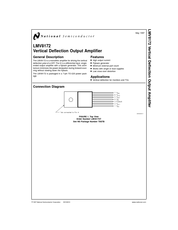
Connection Diagram
DS100010-1
FIGURE 1. Top View Order Number LMV8172T See NS Package Number TA07B
© 1997 National Semiconductor Corporation
DS100010
.national.
Absolute Maximum Ratings
3)
(Notes 1,
TC = 90˚C Thermal Resistance (θJC) Junction Temperature (TJMAX) ESD Susceptibility (Note 5) Storage Temperature Lead Temperature (Soldering 10 seconds)
20W 3˚C/W 150˚C 2 k V
- 65˚C to +80˚C 265˚C (Note 2)
- 20˚C ≤ TJ ≤ +150˚C
Above 25˚C, derate based on θJC and TJ (Note 4)
If Military/Aerospace specified devices are required, please contact the National Semiconductor Sales Office/ Distributors for availability and specifications. Supply Voltage, (VS = VCC1
- VEE) Flyback Peak Voltage, (VOUT
- VEE) (VCC2
- VEE) Input Voltage, (VDC) Pins 1, 7 Output Peak Current, (IO) Pin 5 (Note 8) Power Dissipation (PD) TC = 25˚C 60V 60V VEE ≤ VIN ≤ VCC1 3.2 App 41W 35V
Operating Ratings
Junction Temperature Range
Electrical Characteristics
VCC1 = +17.5V; VCC2 = +16.9V; VEE =
- 17.5V; TC = 25˚C unless otherwise specified. Symbol I2+6 I1 Ios V3L V5L V5H Parameter Total Quiescent Current (I2 + I6) Input Bias Current Input Offset Current Pin 3 Saturation Voltage to VEE Output Saturation Voltage to VEE Output Saturation Voltage to VCC2 See Figure 3, I3 = 20 m A See Figure 3, I5 = 1.2A I5 = 0.7A See Figure 4, I5 =
- 1.2A I5 =
- 0.7A Conditions See Figure 2 Typical (Note 6) 11 -0.5 0.5 1.1 1.3 0.7 2.6 2.1 Limit (Note 7) 20 -2.0 3.0 2.0 2.5...