MF4CN-50
MF4CN-50 is MF4 4th Order Switched Capacitor Butterworth Lowpass Filter manufactured by National.
MF4 4th Order Switched Capacitor Butterworth Lowpass Filter
July 1999
MF4 4th Order Switched Capacitor Butterworth Lowpass Filter
General Description
The MF4 is a versatile, easy to use, precision 4th order Butterworth low-pass filter. Switched-capacitor techniques eliminate external ponent requirements and allow a clock-tunable cutoff frequency. The ratio of the clock frequency to the low-pass cutoff frequency is internally set to 50 to 1. A Schmitt trigger clock input stage allows two clocking options, either self-clocking (via an external resistor and capacitor) for stand-alone applications, or for tighter cutoff frequency control an external TTL or CMOS logic patible clock can be applied. The maximally flat passband frequency response together with a DC gain of 1 V/V allows cascading MF4 sections together for higher order filtering.
Features n n n n n n n n n Low Cost Easy to use 8-pin mini-DIP or 14-pin wide-body S.O. No external ponents 5V to 14V supply voltage Cutoff frequency range of 0.1 Hz to 20 k Hz Cutoff frequency accuracy of ± 0.3% typical Cutoff frequency set by external clock Separate TTL and CMOS/Schmitt-trigger clock inputs
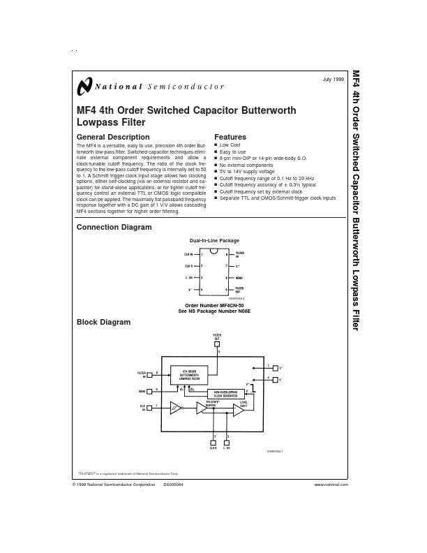
Connection Diagram
Dual-In-Line Package
DS005064-2
Order Number MF4CN-50 See NS Package Number N08E
Block Diagram
DS005064-1
TRI-STATE ® is a registered trademark of National Semiconductor Corp.
© 1999 National Semiconductor Corporation
DS005064
.national.
Block Diagram
Pin Pin Name CLK IN
(Continued)
Pin
Pin Name FILTER IN
Function The input to the low-pass filter. To minimize gain errors the source impedance that drives this input should be less than 2K (see section 1.3 of the Application Hints). For single supply operation the input signal must be biased to mid-supply or AC coupled through a capacitor.
Pin Descriptions
Function A CMOS Schmitt-trigger input to be used with an external CMOS logic level clock. Also used for self clocking Schmitt-trigger oscillator (see section 1.1). A TTL logic...