LM5101A
LM5101A is High Voltage High Side and Low Side Gate Drivers manufactured by National Semiconductor.
- Part of the LM5100B comparator family.
- Part of the LM5100B comparator family.
Description
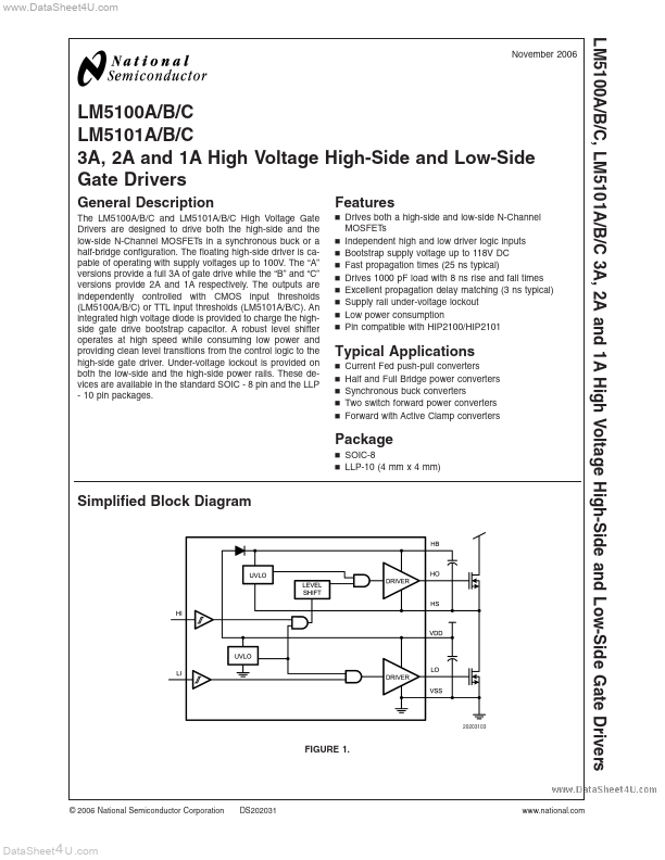
The LM5100A/B/C and LM5101A/B/C High Voltage Gate Drivers are designed to drive both the high-side and the low-side N-Channel MOSFETs in a synchronous buck or a half-bridge configuration. The floating high-side driver is capable of operating with supply voltages up to 100V. The “A” versions provide a full 3A of gate drive while the “B” and “C” versions provide 2A and 1A respectively. The outputs are independently controlled with CMOS input thresholds (LM5100A/B/C) or TTL input thresholds (LM5101A/B/C). An integrated high voltage diode is provided to charge the highside gate drive bootstrap capacitor. A robust level shifter operates at high speed while consuming low power and providing clean level transitions from the control logic to the high-side gate driver. Under-voltage lockout is provided on both the low-side and the high-side power rails. These devices are available in the standard SOIC
- 8 pin and the LLP
- 10 pin packages.
Features n Drives both a high-side and low-side N-Channel MOSFETs n Independent high and low driver logic inputs n Bootstrap supply voltage up to 118V DC n Fast propagation times (25 ns typical) n Drives 1000 p F load with 8 ns rise and fall times n Excellent propagation delay matching (3 ns typical) n Supply rail under-voltage lockout n Low power consumption n Pin patible with HIP2100/HIP2101
Typical Applications n n n n n Current Fed push-pull converters Half and Full Bridge power converters Synchronous buck converters Two switch forward power converters Forward with Active Clamp converters
Package n SOIC-8 n LLP-10 (4 mm x 4 mm)
Simplified Block Diagram
FIGURE 1.
© 2006 National Semiconductor Corporation
DS202031
.national.
Data Sheet 4 U .
..
LM5100A/B/C, LM5101A/B/C
Input/Output Options
Part Number LM5100A LM5101A LM5100B LM5101B LM5100C LM5101C Input Thresholds CMOS TTL CMOS TTL CMOS TTL Peak Output Current 3A 3A 2A 2A 1A 1A
Connection Diagrams
FIGURE 2.
Ordering Information
Orde...