LP5952
LP5952 is Dual Rail Linear Regulator manufactured by National Semiconductor.
Description
The LP5952 is a Dual Supply Rail Linear Regulator optimized for powering ultra-low voltage circuits from a single Li-Ion cell or 3 cell Ni MH/Ni Cd batteries. In the typical post regulation application VBATT is directly connected to the battery (range 2 5.5V) and VIN is supplied by the output voltage of the DC-DC Converter (range 0 4.5V). The device offers superior dropout and transient features bined with very low quiescent currents. In shutdown mode (Enable pin pulled low) the device turns off and reduces battery consumption to 0.1µA (typ.). The LP5952 also features internal protection against overtemperature, over-current and under-voltage conditions. Performance is specified for a -40°C to 125°C junction temperature range. The LP5952 is available in a micro SMD package, lead free. The device is available in fixed output voltages in the range of 0.5V to 2.0V. For availability, please contact your local NSC sales office.
Features
- -
- -
- -
- -
- -
- -
- -
- -
- Excellent load transient response: ±15m V typical Excellent line transient response: ±1m V typical 0.7V ≤ VIN ≤ 4.5V 2.5V ≤ VBATT ≤ 5.5V 0.5V ≤ VOUT ≤ 2.0V For ILOAD = 350m A: VBATT ≥ VOUT(NOM) + 1.5V or 2.5V whichever is higher For ILOAD = 150m A: VBATT ≥ VOUT(NOM) + 1.3V or 2.5V whichever is higher 50µA typical quiescent current from VBATT 10µA typical quiescent current from VIN 0.1µA typical quiescent current in shutdown Guaranteed 350m A output current Noise voltage = 100µVRMS typical Operates from a single Li-Ion cell or 3 cell Ni MH/Ni Cd batteries Only one or two tiny surface-mount external ponents required depending on application Small 5 bump micro SMD package, lead free Thermal-overload and short-circuit protection -40°C to +125°C junction temperature range
Applications
- -
- -
- -
Mobile Phones Hand-Held Radios Personal Digital Assistants Palm-Top PCs Portable Instruments Battery Powered Devices
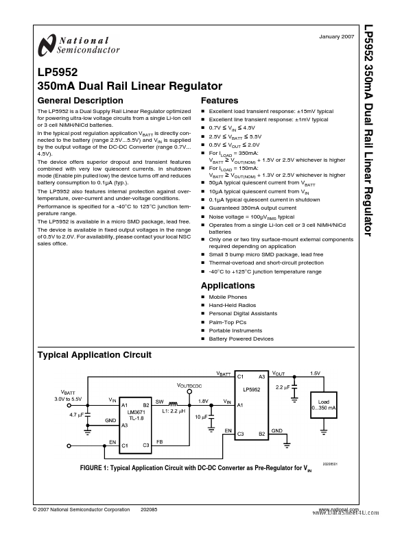
Typical Application Circuit
FIGURE 1: Typical Application Circuit with...