New Japan Radio JRC2901
The two-stage common-emitter output circuit provides gain and output sink capacity of 6mA at an output level of 400mV.The output collector is left open,permitting the designer to drive devices in the range of 2V to 36V.| Part No. | JRC2901 |
|---|---|
| Datasheet | JRC2901 Download |
| Manufacturer |  New Japan Radio |
| Description | NJM2901 |
| Buy | Stock & Price |
GENERAL DESCRIPTION
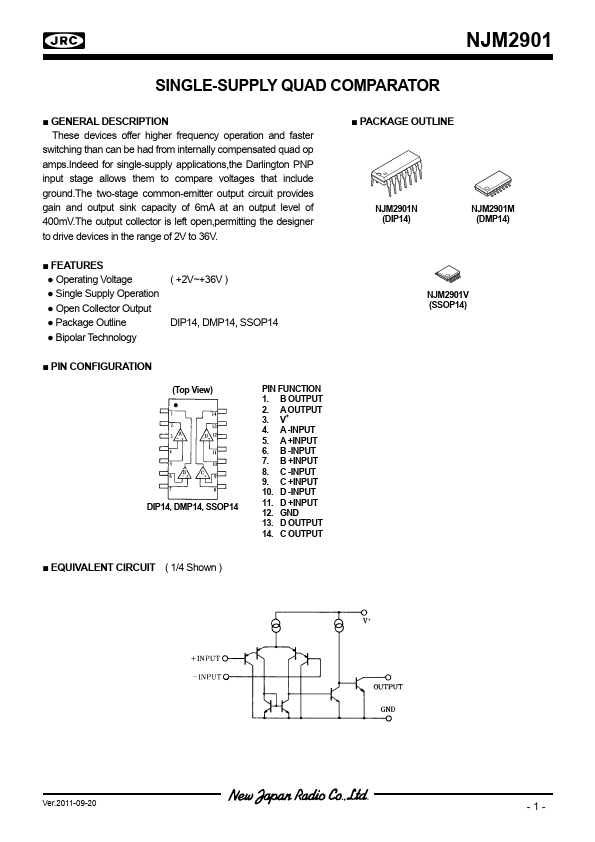
These devices offer higher frequency operation and faster switching than can be had from internally compensated quad op amps.Indeed for single-supply applications,the Darlington PNP input stage allows them to compare voltages that include ground.●
FEATURES
● Operating Voltage● Single Supply Operation
● Open Collector Output
● Package Outline
● Bipolar Technology ( +2V~+36V ) DIP14, DMP14, SSOP14
● PIN CONFIGURATION (Top View) DIP14, DMP14, SSOP14 PIN FUNCTION 1. B OUTPUT 2. A OUTPUT 3. V+ 4. A -INPUT 5. A +INPUT 6. B -INPUT 7. B +INPUT 8. C -INPUT 9. C +INPUT 10. D -INPUT 11. D +INPUT 12. GND 13. D OUTPUT 14. C OUTPUT
● PACKAGE OUTLINE NJM2901N (DIP14) NJM2901M (DMP14) NJM2901V (SSOP14)
● EQUIVALENT CIRCUIT ( 1/4 Shown ) Ver.2011-09-20 -1- NJM2901
●
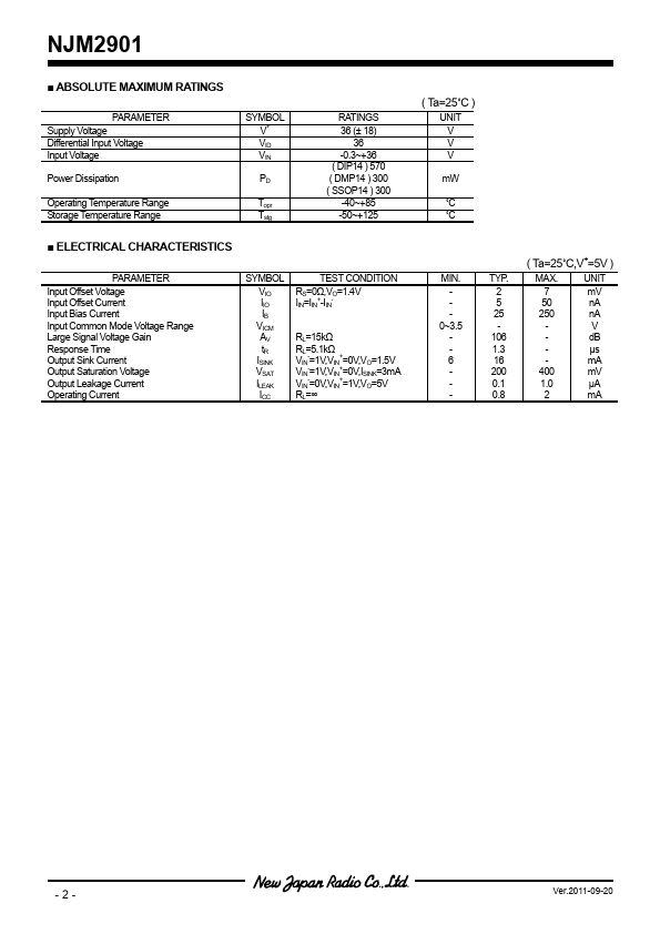
ABSOLUTE MAXIMUM RATINGS
PARAMETER Supply Voltage Differential Input Voltage Input Voltage Power Dissipation Operating Temperature Range Storage Temperature Range SYMBOL V+ VID VIN PD Topr Tstg RATINGS 36 (± 18) 36 -0.