MSA180
MSA180 is Piezo Speaker Amplifier manufactured by OKI Electric.
DESCRIPTION
The MSA180 is a piezo speaker driver for OKI's speech synthesizers. Its voltage gain can be adjusted by a factor of up to 10. The differential output provides an amplitude of twice the voltage supply. A separate output connects to the base of an external transistor for controlling system voltage. A standby function eliminates power loss when no input signal is present.
FEATURES
- Power supply voltage : 2.0 V to 6.0 V (single supply voltage)
- Low current consumption : 4.2 m A typ (VCC=3 V, no load)
- Standby current : <1 m A
- Differential output : Twice the supply voltage (maximum output amplitube)
- Package options : 8-pin plastic DIP (DIP8-P-300-2.54) (Product name: MSA180RS) 8-pin plastic SOP (SOP8-P-250-1.27-K) (Product name: MSA180MS-K) Chip
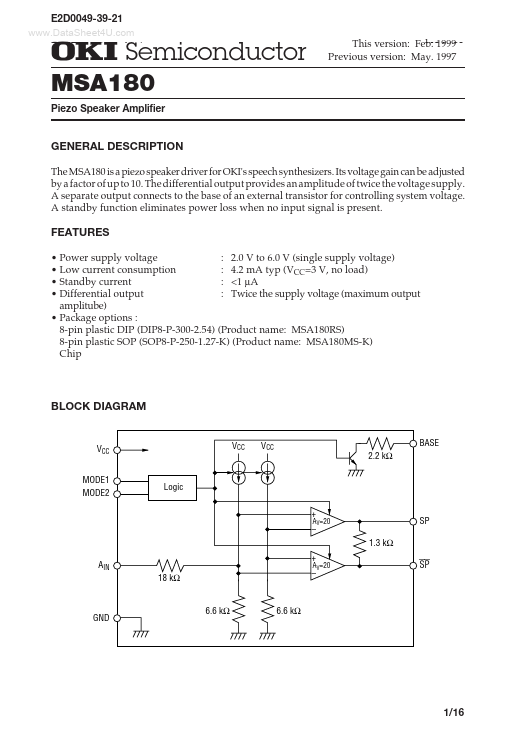
BLOCK DIAGRAM
BASE 2.2 k W
VCC MODE1 MODE2
Logic +
- + 18 k W
- AV=20
SP 1.3 k W
AV=20
6.6 k W
6.6 k W
1/16
¡ Semiconductor
PIN CONFIGURATION (TOP VIEW)
MODE2 1 AIN 2 GND 3 SP 4 8 MODE1 7 BASE 6 VCC 5 SP
8-Pin Plastic DIP or 8-Pin Plastic SOP
PIN DESCRIPTIONS
Pin 6 3 2 Symbol VCC GND AIN Type
- - I Power supply pin. Ground pin. Voice signal input pin. This pin switches the device between operation and standby modes. 8 MODE1 I The IC is in operation mode if VIH > 1.0 V on the MODE1 pin and is in standby mode if VIL < 0.3 V on the MODE1 pin. When MODE1 is used, MODE2 must be connected to VCC. This pin switches the device between operation and standby modes. 1 MODE2 I The IC is in operation mode if VIL < VCC- 1.0 V on MODE1 pin and is in standby mode if VIH > VCC- 0.3 V on MODE1 pin. When MODE2 is used MODE1 must be connected to GND. This pin is connected to the base of an external transistor. If an 7 BASE O external transistor is not used to control system voltage, this pin must be left open. 4 5 SP SP O O This is a speaker output pin that provides signals with the same phase as the input. This is a speaker output pin that provides signals with an inverted phase to the input....