CS52843
CS52843 is Current Mode PWM Control Circuit manufactured by onsemi.
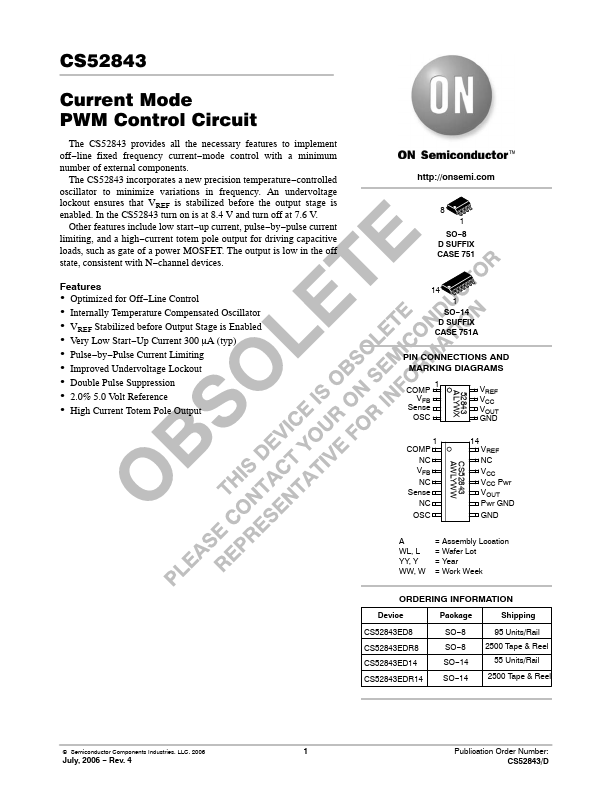
features to implement off- line fixed frequency current- mode control with a minimum number of external ponents. The CS52843 incorporates a new precision temperature- controlled oscillator to minimize variations in frequency. An undervoltage lockout ensures that VREF is stabilized before the output stage is enabled. In the CS52843 turn on is at 8.4 V and turn off at 7.6 V. Other features include low start- up current, pulse- by- pulse current limiting, and a high- current totem pole output for driving capacitive loads, such as gate of a power MOSFET. The output is low in the off state, consistent with N- channel devices. http://onsemi.
8 1 SO- 8 D SUFFIX CASE 751
- -
- -
- -
- -
- Features
Optimized for Off- Line Control Internally Temperature pensated Oscillator VREF Stabilized before Output Stage is Enabled Very Low Start- Up Current 300 μA (typ) Pulse- by- Pulse Current Limiting Improved Undervoltage Lockout Double Pulse Suppression 2.0% 5.0 Volt Reference High Current Totem Pole Output
14 1 SO- 14 D SUFFIX CASE 751A
PIN CONNECTIONS AND MARKING DIAGRAMS
P VFB Sense OSC 1 52843 ALYWX 1 CS52843 AWLYWW 14 VREF VCC VOUT GND
P NC VFB NC Sense NC OSC A WL, L YY, Y WW, W
VREF NC VCC VCC Pwr VOUT Pwr GND GND
= Assembly Location = Wafer Lot = Year = Work Week
ORDERING INFORMATION
Device CS52843ED8 CS52843EDR8 CS52843ED14 CS52843EDR14 Package SO- 8 SO- 8 SO- 14 SO- 14 Shipping 95 Units/Rail 2500 Tape & Reel 55 Units/Rail 2500 Tape & Reel
© Semiconductor ponents Industries, LLC, 2006
July, 2006
- Rev. 4
Publication Order Number: CS52843/D
VCC Undervoltage Lockout
VCC Pwr
34 V GND 8.4 V/7.6 V
Set/ Reset
5.0 Volt Reference
VREF
Internal Bias VFB Error Amplifier R 2.50 V
- Oscillator S R R Sense 1.0 V Current Sensing parator PWM Latch Pwr GND 2R + OSC
OUTPUT ENABLE
R NOR VOUT
Figure 1. Block Diagram MAXIMUM RATINGS-
Rating Supply Voltage (ICC < 30 m A) Supply Voltage (Low Impedance Source) Output Current Output Energy (Capacitive Load) Analog Inputs...