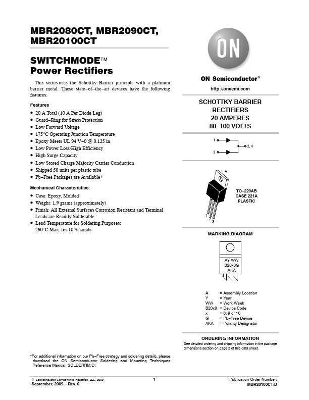
- Part: MBR20100CT
- Description: Power Rectifiers
- Manufacturer: onsemi
- Size: 119.15 KB
Overview
- 20 A Total (10 A Per Diode Leg)
- Guard-Ring for Stress Protection
- Low Forward Voltage
- 175°C Operating Junction Temperature
- Epoxy Meets UL 94 V-0 @ 0.125 in
- Low Power Loss/High Efficiency
- High Surge Capacity
- Low Stored Charge Majority Carrier Conduction
- Shipped 50 units per plastic tube
- Pb-Free Packages are Available* Mechanical Characteristics:
Datasheets by Manufacturer
- MBR20100CT — International Rectifier — SCHOTTKY RECTIFIER
- MBR20100CT-E3 — Vishay — Dual Common-Cathode High Voltage Trench MOS Barrier Schottky Rectifier
- MBR20100CT-Y — Taiwan Semiconductor — Dual Common Cathode Schottky Rectifier
- MBR20100CT — Taiwan Semiconductor — Dual Common Cathode Schottky Rectifier
- MBR20100CT — Mospec Semiconductor — Schottky Barrier Rectifier
- MBR20100CT — Inchange Semiconductor — Schottky Barrier Rectifier
- MBR20100CT — Frontier Electronics — 20A SCHOTTKY BARRIER RECTIFIERS
- MBR20100CT — Motorola Semiconductor — SWITCHMODE Power Rectifiers
- MBR20100CT — Micro Commercial Components — 20 Amp Schottky Barrier Rectifier
- MBR20100CT — Thinki Semiconductor — Schottky Barrier Rectifiers