Pin Symbol
Function
1
Demag
Core reset detection and OVP
2 FB Sets the peak current setpoint
3 CS Current sense input and skip cycle level selection
4 GND 5 Drv 6 VCC 7 NC 8 HV
The IC ground Driving pulses Supplies the IC
--
High--voltage pin
Description
The auxiliary FLYBACK signal ensure
Key Features
an efficient protective circuitry that, in presence of an overcurrent condition, disables the output pulses and enters a safe burst mode, trying to restart. Once the default has gone, the device auto- recovers. Finally an internal 1.0 ms Soft- Start eliminates the traditional startup stress. The NCP1378 is tailored for low voltage.
Full PDF Text Transcription for NCP1378 (Reference)
Note: Below is a high-fidelity text extraction (approx. 800 characters) for
NCP1378. For precise diagrams, and layout, please refer to the original PDF.
NCP1378 
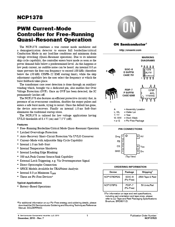
PWM Current- Mode Controller for Free- Running Quasi- Resonant Operation The NCP1378 combines a true current mode modulator and a demagnetization detector to ensu...
View more extracted text
s a true current mode modulator and a demagnetization detector to ensure full borderline/critical Conduction Mode in any load/line conditions and minimum drain voltage switching (Quasi- Resonant operation). Due to its inherent skip cycle capability, the controller enters burst mode as soon as the power demand falls below a predetermined level. As this happens at low peak current, no audible noise can be heard. An internal 8.0 ms timer prevents the free- run frequency to exceed 100 kHz (therefore below the 150 kHz CISPR- 22 EMI starting limit), while the skip adjustment capability lets the user select the frequency at which