NCP1400A Overview
Key Specifications
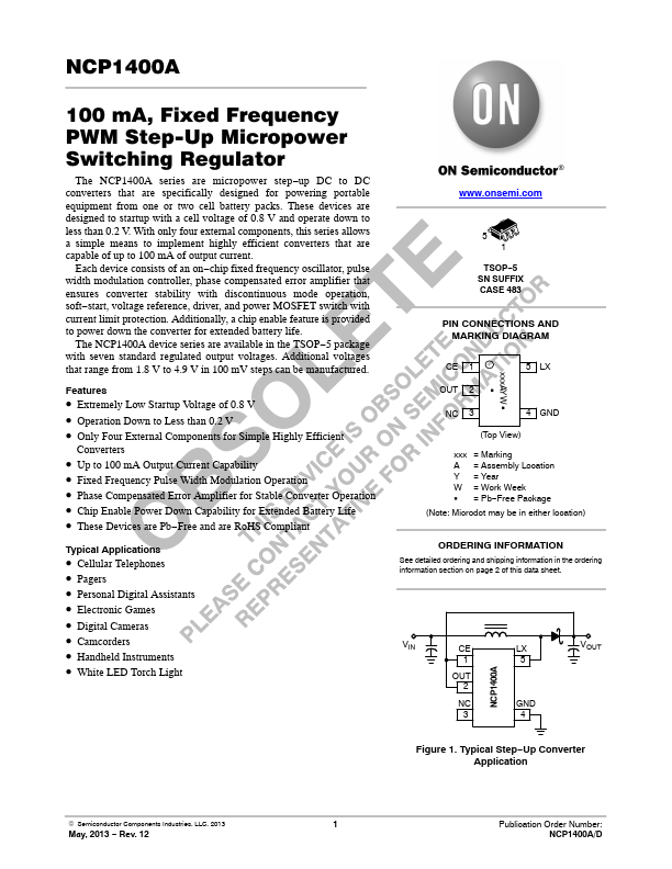
Package: TSSOP
Mount Type: Surface Mount
Pins: 5
Max Voltage (typical range): 6 V
Key Features
- Extremely Low Startup Voltage of 0.8 V
- Operation Down to Less than 0.2 V
- Only Four External Components for Simple Highly Efficient Converters
- Up to 100 mA Output Current Capability
- Fixed Frequency Pulse Width Modulation Operation