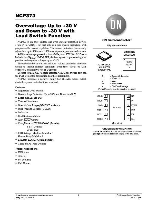
Datasheet Details
| Part number | NCP373 |
|---|---|
| Manufacturer | ON Semiconductor |
| File Size | 170.92 KB |
| Description | Over-Voltage and Over-Current protection device |
| Datasheet |
|
|
|
|
| Part number | NCP373 |
|---|---|
| Manufacturer | ON Semiconductor |
| File Size | 170.92 KB |
| Description | Over-Voltage and Over-Current protection device |
| Datasheet |
|
|
|
|
Pin Pin Name Type 1,2 VBUS POWER 3 GND POWER 4 RES1 INPUT 5 RES2 INPUT 6 RES3 INPUT 7 Ilim OUTPUT Description VBUS voltage pins: must be hardwired together on the PCB.These pins are connected to the VBUS connector, and are protected against positive and negative overvoltage events.A 1 mF low ESR ceramic capacitor, or larger, must be connected between these pins and GND.Ground Reserved pin.Must be connected to GND potential and used for IC test.Reserved pin.Must be connected to G
📁 Similar Datasheet