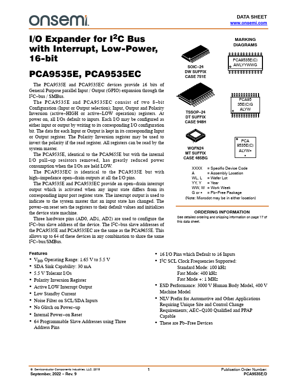
Datasheet4U Logo Datasheet4U.com

PCA9535E - 16-bit Low-Power I/O Expander

General Description

Pin Symbol SOIC24, TSSOP24 INT 1 AD1 2 AD2 3 IO0_0 4 IO0_1 5 IO0_2 6 IO0_3 7 IO0_4 8 IO0_5 9 IO0_6 10 IO0_7 11 VSS 12 IO1_0 13 IO1_1 14 IO1_2 15 IO1_3 16 IO1_4 17 IO1

Key Features

  • VDD Operating Range: 1.65 V to 5.5 V.
  • SDA Sink Capability: 30 mA.
  • 5.5 V Tolerant I/Os.
  • Polarity Inversion Register.
  • Active LOW Interrupt Output.
  • Low Standby Current.
  • Noise Filter on SCL/SDA Inputs.
  • No Glitch on Power.
  • up.
  • Internal Power.
  • on Reset.
  • 64 Programmable Slave Addresses using Three Address Pins.
  • 16 I/O Pins which Default to 16 Inputs.
  • I2C SCL Clock Frequencies Supported: Standard Mode: 100 kHz Fast Mode: 400 kHz.

📥 Download Datasheet

Datasheet Details

Part number PCA9535E
Manufacturer onsemi
File Size 385.19 KB
Description 16-bit Low-Power I/O Expander
Datasheet download datasheet PCA9535E Datasheet

Full PDF Text Transcription (Reference)

The following content is an automatically extracted verbatim text from the original manufacturer datasheet and is provided for reference purposes only.

View original datasheet text
DATA SHEET www.onsemi.com I/O Expander for I2C Bus with Interrupt, Low-Power, 16-bit PCA9535E, PCA9535EC The PCA9535E and PCA9535EC devices provide 16 bits of General Purpose parallel Input / Output (GPIO) expansion through the I2C−bus / SMBus. The PCA9535E and PCA9535EC consist of two 8−bit Configuration (Input or Output selection); Input, Output and Polarity Inversion (active−HIGH or active−LOW operation) registers. At power on, all I/Os default to inputs. Each I/O may be configured as either input or output by writing to its corresponding I/O configuration bit. The data for each Input or Output is kept in its corresponding Input or Output register. The Polarity Inversion register may be used to invert the polarity if the read register. All registers can be read by the system master.