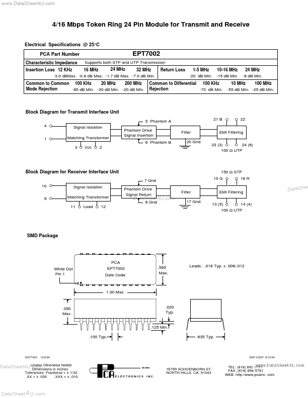
@ 25°C PCA Part Number Characteristic Impedance EPT7002 Supports both STP and UTP Transmission Return Loss 1-5 MHz 10-16 MHz -20 dB Min. -15 dB Min. 24 MHz -8 dB Min. 24 MHz Insertion Loss 12 KHz 16 MHz 32 MHz -3.0 dBMax. -0.8 dB Max. -1.7 dB Max. -7.0 dB Min. Common to Common 100 KHz 20 MHz 200 MHz Mode Rejection -65 dB Min. -30 dB Min. -20 dB Min. Common to Differential 100 KHz Rejection -70 dB Min. 10 MHz 100 MHz -55 dB Min. -25 dB Min. Block Diagram for Transmit Interface Unit 5 Phantom A 4 1 Signal Isolation Matching Transformer 3 Vcc 2 Phantom Drive Signal Insertion 6 Phantom B Filter 20 Gnd 21 B 22 EMI Filtering 24 (6) 23 (3) 100 Ω UTP Block Diagram for Receiver Interface Unit 7 Gnd 10 9 Signal Isolation Matching Transformer 11 Load 12 Phantom Drive Signal Return Filter 17 Gnd 150 Ω STP 15 G 16 R EMI Filtering 13 (5) 14 (4) 100 Ω UTP e DataShe DataSheet4U.com 8 Gnd SMD Package White Dot Pin 1 PCA EPT7002 Date Code .585 Max. Leads : .018 Typ. x .008/.012 1.30 Max. .350 Max. .020 Typ. .125 Min. .100 Typ. .635 Typ.
This website uses cookies or similar technologies, to enhance your browsing experience and provide personalized recommendations. By continuing to use our website, you agree to our Privacy Policy