PDI D10040180GTH
The slope is defined as the difference between the gain at the start frequency and the gain at the stop frequency.| Part No. | D10040180GTH |
|---|---|
| Datasheet | D10040180GTH Download |
| Manufacturer |  PDI |
| Description | GaAs Power Doubler |
| Buy | Stock & Price |
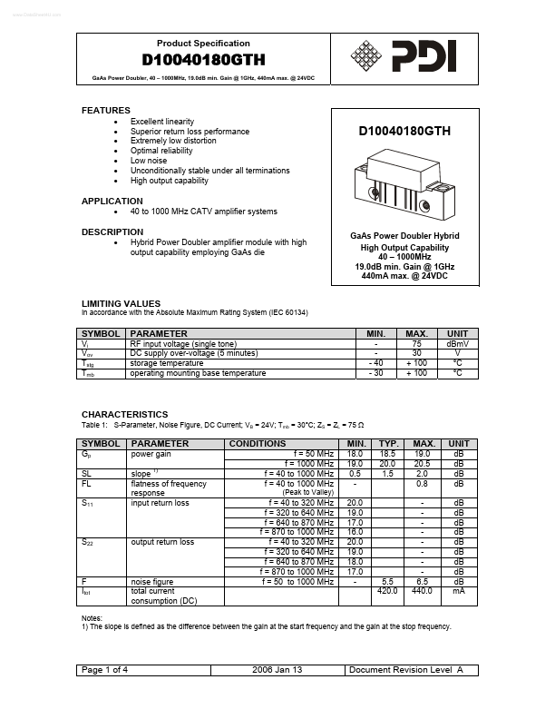
FEATURES
●●
●
●
●
●
● Excellent linearity Superior return loss performance Extremely low distortion Optimal reliability Low noise Unconditionally stable under all terminations High output capability D10040180GTH APPLICATION
● 40 to 1000 MHz CATV amplifier systems GaAs Power Doubler Hybrid High Output Capability 40 – 1000MHz 19.0dB min. Gain @ 1GHz 440mA max. @ 24VDC
DESCRIPTION
● Hybrid Power Doubler amplifier module with high output capability employing GaAs die LIMITING VALUES In accordance with the Absolute Maximum Rating System (IEC 60134) SYMBOL Vi Vov Tstg Tmb PARAMETER RF input voltage (single tone) DC supply over-voltage (5 minutes) storage temperature operating mounting base temperature MIN. - 40 - 30 MAX. 75 30 + 100 + 100 UNIT dBmV V °C °C CHARACTERISTICS Table 1: S-Parameter, Noise Figure, DC Current; VB = 24V; Tmb = 30°C; ZS = ZL = 75 Ω SYMBOL Gp SL FL S11 PARAMETER power gain slope 1) flatness of frequency response input return loss CONDITIONS f = 50 MHz f = 1000 MHz f = 40 to 1000 MHz f = 40 to 1000 MHz (Peak to Valley) MIN.