PDI S8740200P
The slope is defined as the difference between the gain at the start frequency and the gain at the stop frequency.| Part No. | S8740200P |
|---|---|
| Datasheet | S8740200P Download |
| Manufacturer |  PDI |
| Description | GaAs Push Pull Hybrid |
| Buy | Stock & Price |
FEATURES
●●
●
●
●
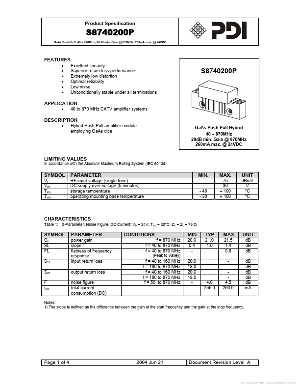
● Excellent linearity Superior return loss performance Extremely low distortion Optimal reliability Low noise Unconditionally stable under all terminations S8740200P APPLICATION
● 40 to 870 MHz CATV amplifier systems
DESCRIPTION
● Hybrid Push Pull amplifier module employing GaAs dice GaAs Push Pull Hybrid 40 – 870MHz 20dB min. Gain @ 870MHz 260mA max. @ 24VDC LIMITING VALUES In accordance with the Absolute Maximum Rating System (IEC 60134) SYMBOL Vi Vov Tstg Tmb PARAMETER RF input voltage (single tone) DC supply over-voltage (5 minutes) storage temperature operating mounting base temperature MIN. - 40 - 30 MAX. 75 30 + 100 + 100 UNIT dBmV V °C °C CHARACTERISTICS Table 1: S-Parameter, Noise Figure, DC Current; VB = 24V; Tmb = 30°C; ZS = ZL = 75 Ω SYMBOL Gp SL FL S11 S22 F Itot PARAMETER power gain slope 1) flatness of frequency response input return loss output return loss noise figure total current consumption (DC) CONDITIONS f = 870 MHz f = 40 to 870 MHz f = 40 to 870 MHz (Peak to Valley) MIN.